Purpose of the flight and payload description
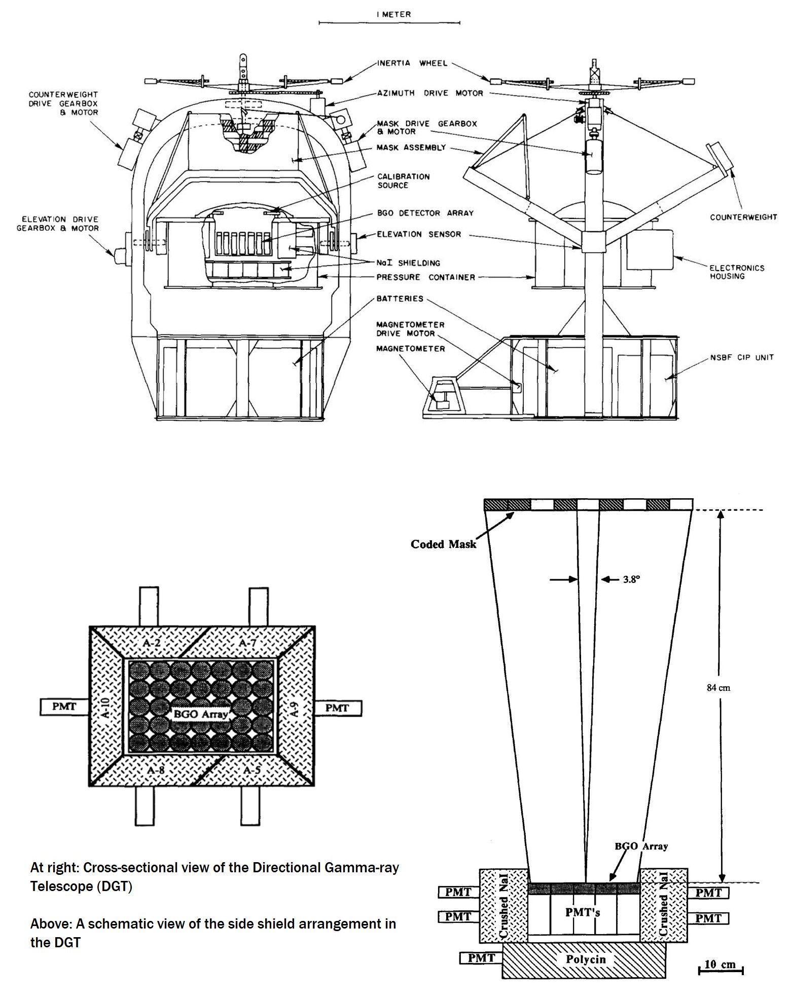
DGT was the acronym for Directional Gamma-ray Telescope an instrument developed in early 1980's at the University of New Hampshire to image celestial gamma-rays over the energy range 160 keV to 9.3 MeV. It used for the first time a technique known as coded aperture imaging in order to obtain spatially resolved images of the sky with an angular resolution of 3.8°. Coded aperture imaging is now a standard technique in high energy astronomy. The DGT design was based very heavily on a previous University of New Hampshire balloon experiment known as the Large Gamma-ray Telescope
The DGT instrument is shown schematically at left (click to enlarge). The detection plane consisted of a 35-element array of bismuth germanate (BGO) scintillation crystals actively shielded from below by 10 cm of Nal Polysem and on the sides by 7.5 cm of Nal. The entire anticoincidence well defined a forward geometric aperture of ~120° FWHM. Each BGO element was a right-circular cylinder 5.1 cm in diameter by 2 cm thick. BGO was chosen in preference to Nal for the detection plane because of its higher sensitivity per unit volume. The coded mask of the DGT was positioned 84 cm above the detection plane and had outside dimensions 72.8 cm by 50.4 cm. Each opaque element of the mask was composed of a 5.6 cm by 5.6 cm block of lead, of thickness 1.9 cm. Such a thickness was sufficient to attenuate 97% of the photon flux at 0.5 MeV and 60% at 2.6 MeV. The pattern of mask elements was based on a 5x7 URA pattern.
The main detector components were contained within a 1/16" thick pressurized aluminum housing which was maintained at a minimum 5 psi during the flight to reduce the potential of high voltage corona discharge. Temperature was controlled within this container using foam insulation and internal heaters. Fans were also used to ensure the efficient removal of the internally-generated heat via convective airflow to the outer surface of the pressure vessel. Power for the experiment was provided by a stack of 100 lithium organic batteries having a total capacity of 200 amp/hours.
The pressurized container (or detector "can") was mounted onto a 0.75" thick support plate which, in turn, was mounted within the supporting arch on the gondola via a 1 1/2" horizontal shaft. This shaft also served as the rotation axis of the central detectors. This mounting was such that the detector assembly could be moved independently in zenith angle over a range of 0° to 85° on either side of the supporting arch. The detector can was driven by a stepping motor in commandable increments. The mask was mounted, parallel to the detector, on a support arm which could be raised and lowered in elevation. In order to maintain a balanced gondola, a second (counterweight) arm was symmetrically mounted with respect to the mask arm and carried identical weight.
Alignment of the mask with the detector array was achieved by the use of infrared optical sensors. The zenith angles of the detector can and the mask/counterweight arms were determined with the use of calibrated potentiometers to an accuracy of ±0.25°. The zenith reference was the local vertical and any offset of the gondola from level was determined by two precision inclinometers which measured pitch and yaw.
Azimuthal orientation of the experiment was obtained by setting an offset flux gate magnetometer to the desired azimuth and torquing an inertia wheel to null the magnetometer. The magnetometer angle was measured with a calibrated potentiometer to an accuracy of ±0.25°. The inertia wheel drive signal was pulsed at a frequency determined by the offset angle and its rate of change. Due to both the effects of the balloon rotation and thermal effects on the gondola support bearings, the experiment oscillated in azimuth about the magnetometer null point with an RMS amplitude of ~3.0°. A second magnetometer, fixed with respect to the gondola, gave coarse verification of the pointing direction throughout the flight. Two sun sensors of different designs were mounted on the mask arm to periodically check the ponting zenith and azimuth during the daytime portion of the flight.
The total gondola weight, including batteries, crash padding and NSBF electronics (telemetry) was about 1735 pounds (790 kg).
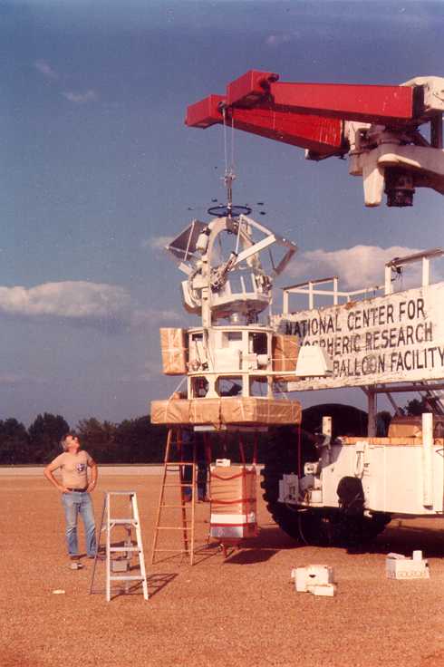
Video footage from the KXAS-TV/NBC showing DGT's launch
Details of the balloon flight
Balloon launched on: 9/30/1982 at 00:36 utc
Launch site: Columbia Scientific Balloon Facility, Palestine, Texas, US
Balloon launched by: National Scientific Balloon Facility (NSBF)
Balloon manufacturer/size/composition: Zero Pressure Balloon Winzen - 726.614 m3 (15.24 microns) SF408.33-060-NSCR-01
Balloon serial number: W25.66-2-01
Flight identification number: 1311P
End of flight (L for landing time, W for last contact, otherwise termination time): 9/30/1982 at 1:42 utc
Balloon flight duration (F: time at float only, otherwise total flight time in d:days / h:hours or m:minutes - ): ~1 h
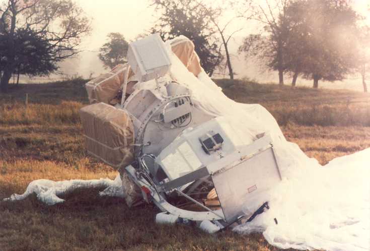
Landing site: Balloon failure at 60.000 ft. Landing 20 miles SW of Frankston, Texas, US
Payload weight: 1059 kgs
Overall weight: 1600 kgs
The DGT was launched as flight 1311-P from the National Scientific Balloon Facility in Palestine, Texas on September 30, 1982 at 00:36 UTC. An hour into the flight, during ascent through the tropopause the balloon suffered a catastrophic failure. No useful scientific data was obtained. Attempts to extrapolate the observed background rates to those expected at float altitude met with limited success. The payload landed 20 miles SW of Frankston, Texas.
External references
- A Balloon-Borne Coded Aperture Telescope for Low-Energy Gamma- Ray Astronomy Nuclear Instruments and Methods in Physics Research A274 (1989) 362
- Gamma-ray imaging observations of the Crab and Cygnus regions Ph.D Thesis by Mark Lewis McConnell, University of New Hampshire, 1987
- National Scientific Balloon Facility Annual Report FY 1982 National Center for Atmospheric Research, February 1983
- Observations of cosmic gamma ray sources and their contribution to the diffuse gamma ray background Ph.D Thesis by Debadarshi Bhattacharya, University of New Hampshire, 1990
- The Directional Gamma-Ray Telescope (DGT) Alan Owens website (now available via Archive.Org)
Images of the mission
If you consider this website interesting or useful, you can help me to keep it up and running with a small donation to cover the operational costs. Just the equivalent of the price of a cup of coffee helps a lot.
