Purpose of the flight and payload description
This instrument was part of NASA's program to investigate the seriousness of man-made stratospheric ozone depletion via high altitude aircraft exhaust or the release of chlorofluorcarbons into the lower atmosphere. Specific goal of the balloon-borne LIDAR was to measure of ozone and hydroxyl radical in the stratosphere.
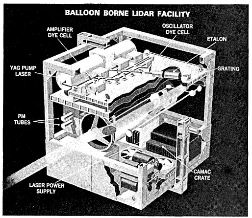
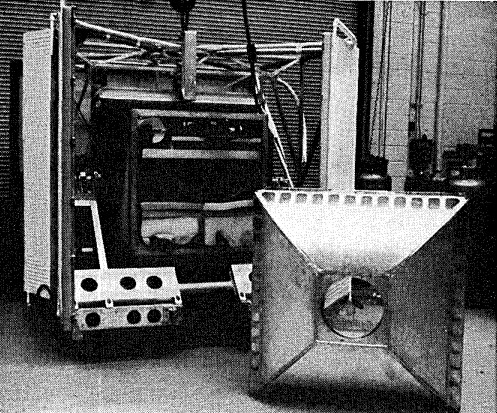
In a brief resume, the instrument consisted of a frequency-doubled tunable dye laser pumped by a Nd:YAG laser, a multiwavelength detector comprised of a 12-inches Cassegrainian telescope coupled to a modified 1/4 meter spectrometer, and a gated detection system. The entire assembly was housed in a pressurized temperature regulated container.
The LIDAR system itself (scheme at left) used two different techniques to acomplish its measurements. Hydroxyl radical was measured using remote laser induced fluorescence in which a wavelength was emitted which excited the species under investigation to fluoresce. By relating the intensity of the fluorescence wavelength following a laser pulse the species concentration was inferred. 282 nm was the exciting wavelength and fluorescence was monitored in a band from 305 nm through 315 nm. Ozone was measured by the technique of differential absorption LIDAR (DIAL) in which two wavelengths were transmitted simultaneously and their backscattered intensities were measured. Choosing one wavelength which was absorbed by the species under study and the other wavelength in an unattenuated portion of the spectum allowed to infer the species concentration along the path of the laser beams from the relative intensities of the backscatter. Since 282 nm -which was already in use for the hydroxyl radical measurement- was absorbed by ozone, it was chosen for the first wavelength. 355 nm was chosed for the second wavelength for reasons of convenience.
The laser source for the 282 nm was a frequency doubled tuneable dye laser pumped by a doubled Nszag laser. The dye laser was an oscíllator amplifier system with off axis longitudinal pumping and an etalon-diffraction grating tuning system. 355 nm was produced by frequency tripling the micron radiation from the Nszag laser. After generation, these two wavelengths were combined using a dichroic mirror, expanded in an all reflective telescope to reduce beam divergence and transmitted along the axis of a 30 cm diameter Cassegrain telescope used as the receiver. The light returning following a laser pulse was collected by the telescope and focussed on the entrance aperture of a 1/4 meter monochromator. This monochromator had three exit apertures for the three detected wavelengths 282 nm, 305-315 nm and 355 nm. Light at each wavelength was detected by a separate photomultiplier tube. Output from the tubes was sampled and stored in high speed buffers awaiting transmission to the ground between laser shots. Data taking was controlled by an onboard microprocessor.
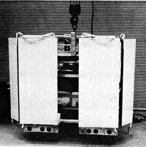
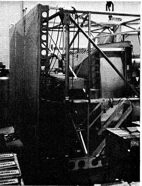
The gondola which supported the lidar system was, for the most part, constructed of aluminum (see figures at right). The outer framework formed a cube 2 meters per side. The girder base and the front face of the cube had a continuous opening ~ 45 cm wide to allow an unobstructed view for the lidar for elevations from straight down to 60º up. The framework supported two radiator panels on the front (each side of the 45-cm slot) and one on the rear. Four steel cables, one from each upper corner of the cube, were attached to a central fitting suspended from an eyelet on the lower portion of the azimuth drive motor. At the rear of the gondola were shelves ~ 30 cm deep and 1.2 m high which housed the batteries, telemetry, and a Dasibi ozone analyzer. The rest of the base platform was occupied by a support frame for the gimbal on which the instrument compartment could rotate in elevation.
The system could be pointed in both azimuth and elevation to permit ranging in any desired direction and to permit minimization of scattered solar flux. Elevation pointing was provided by a harmonic drive system attached to the instrument girth ring at one of the gimbals. The azimuth angle was sensed by an onboard magnetometer and was controlled by rotating the entire gondola. The overall pointing accuracy was of a few degrees, which was more than adequate for the purposes of the lidar.
Power to operate the system electronics and auxiliary systems, was supplied by lithium batteries while silver cells were used for the laser alone, due to its high-peak current requirements. The command and telemetry equipment used a 50-kbit pulse code modulation (PCM) system that collected and transmitted lidar returns, housekeeping and system data (temperatures, battery voltages, etc.). The command system actuated on the gondola throught thirty-two relays that were used for several operations that included turning the laser electronics on and off, overriding thermal systems, tuning the laser, and selecting the lidar operating program and the data sets returned to the ground.
The thermal design for the lidar system was quite complex. The original design involved a combination of active and passive techniques under automatic and ground control to permit adaptation to any operating condition. Each sensitive element was mounted in its own insulated housing with a regulated heating element and set to operate above the ambient temperature. The experiment housing was physically divided into two separate compartments insulated from one another. The upper compartment contained the laser head and the optical components. The lower compartment contained the laser electronics and system power supplies. The bulk of the heat was generated in this lower compartment. Two separate thermostatically controlled cooling loops were provided. For the electronics a liquid-air heat exchanger in the lower compartment with two pumps and two fans was used to transport heat to an external radiator at the rear panel of the gondola.
Details of the balloon flight
Balloon launched on: 10/20/1980 at 15:35 utc
Launch site: Columbia Scientific Balloon Facility, Palestine, Texas, US
Balloon launched by: National Scientific Balloon Facility (NSBF)
Balloon manufacturer/size/composition: Zero Pressure Balloon Winzen 794.288 m3 (20.32 microns - Stratofilm) - SF 415.29-080-NSCR-01
Balloon serial number: W28.05-3-04
Flight identification number: 1224P
End of flight (L for landing time, W for last contact, otherwise termination time): 10/21/1980 at 2:30 utc
Balloon flight duration (F: time at float only, otherwise total flight time in d:days / h:hours or m:minutes - ): F 11 h
Landing site: Free fall of the payload. Impact 2 Miles NW of Bogalusa, Louisiana, US
Payload weight: 2337 kgs
The balloon was launched using the Dynamic method at 10.35 CDT on 20 October 1980. The balloon ascent was slow thus it reached float altitude of 119.000 ft at 14:50 utc CDT. After several hours aloft, the flight path had turned toward the Gulf of Mexico, so at 21.30 CDT the termination command was sent. At that moment, the gondola experimented a free fall and crashed in a field outside Bogalusa, Louisiana. It had burned on
impact and was essentially destroyed.
Failure investigations by NSBF and Goddard concluded that the gondola had experienced the shock of the parachute opening, with an asymmetric load on the cables, snapping one of them and resulting in subsequent separations of the suspension at the other three corners of the gondola.
During the flight, ozone measurements were obtained in the altitude region from 21 to 36 km and hydroxyl radical measurements in the 33 to 36 km region. Althought some overheating forced to turn off the LIDAR from time to time, the results obtained from this first flight have shown LIDAR to be an effective tool for stratospheric investigation. Unfortunately the sytem experienced a uncontrolled free fall (see details below) at the end of its flight and was totally destroyed. A new system incorporating many improvements was built and flight tested in 1982.
External references
- Balloon borne LIDAR measurements of stratospheric hydroxyl radical J. Geophys. Res., 88(C9), 52815289
- National Scientific Balloon Facility Annual Report FY 1981 National Center for Atmospheric Research, April 1982
- Stratospheric ozone and hydroxyl radical measurements by balloon-borne lidar Applied Optics Vol. 21, Issue 12, pp. 2265-2274 (1982)
- The NASA/Goddard Balloon Borne Lidar System Optical and Laser Remote Sensing, Springer Series in Optical Sciences, vol. 39. p.229
Images of the mission
If you consider this website interesting or useful, you can help me to keep it up and running with a small donation to cover the operational costs. Just the equivalent of the price of a cup of coffee helps a lot.
