Purpose of the flight and payload description
The objective of the flight was to study high energy cosmic rays using a combination of a ionization spectrometer with spark chambers and different target materials. The instrument was the result of a collaboration between the Max Planck Institute for Extraterrestrial Physics in Munich, West Germany and Louisiana State University in Baton Rouge, United States.
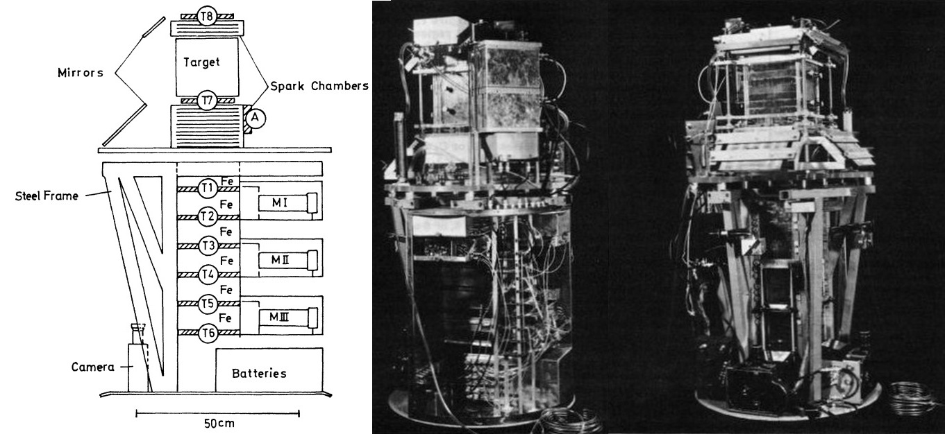
In the figure at left can be seen a schematic drawing of the apparatus (click for more details and pictures). It consisted of two main parts: the spark chambers above and below the target and a ionization spectrometer. A different target material was used in each flight including carbon, lead, nuclear emulsions and mercury.
The spark chambers were multigap chambers (1 mm Al-electrodes with 9 mm spacing). One electrode of each pair was covered by ordinary window glass. This resulted in a greatly increased multiple spark efficiency if neon, helium, or a neon-helium mixture was used as the spark chamber gas. Each time a high energy particle satisfied the trigger requirement, the spark chambers were triggered and photographed using a mirror system and two 16 mm Bolex cameras. The chamber above the target (4 gaps) was used to show the direction of the incoming particle and also to indicate the simultaneous incidence of more than one particle. The chamber below the target (12 gaps) was used to determine whether an interaction had occurred in the target.
The ionization spectrometer consisted of six layers of iron, separated by layers of plastic scintillator each 10 mm thick. One layer of scintillator was also placed beneath the bottom iron absorber. The thickness of each layer of iron was 55 g/cm2, or about one half of an interaction length or 4 radiation lengths (r.1.). The surface area was 18 x 18 cm2. Each of the scintillators in the spectrometer was viewed by two Valvo 53 AVP photomultipliers. Photomultipliers MI, MII, and MIII were used only to measure the light output from the three pairs of scintillators.
Photomultipliers 1-6, each viewing one of the six scintillators, comprised the triggering system along with scintillation-counter 8 above the top spark chamber and scintillation counter 7 just below the target. In order to trigger the spark chambers, a coincidence was required between pulses originating from counters 7 and 8, and a pulse from either of the pairs of scintillators A, B, or C corresponding to the passage of at least 13 particles through scintillators A, B, or C. This last requirement set a minimum energy threshold for the primary particle at about 30 GeV, and it ruled out activation of the trigger system by slow, stopping particles. Scintillation counter 0 was a guard counter for excluding side showers. It was used in anticoincidence.
Upon receiving a signal from the concidence logic circuitry, the spark chambers were triggered and photographed. At the same time, pulses from photomultipliers MI, MII and MIII were measured with three 128 channel analyzers which had logarithmic response over a three decade range of pulse heights. The measured pulse heights were then digitized and displayed using a system of small light bulbs which were photographed together with the spark chambers. Scintillation counter 8, on top of the apparatus, was also used to measure the charge of the incoming particle in four channels corresponding to charges Z = 1, Z = 2, Z = 3, and Z > 4. This information, too, was displayed on small lamps and photographed.
In addition, counter 7 was used to indicate whether one or more than one particle emerged from the target. Finally, each of the trigger counters I through 6 had two discriminator levels which were used in conjunction with small light bulbs to indicate whether or not more than two particles (low level) or more than thirteen particles (high level) had penetrated each scintillator. This provided additional information about the cascade development in the spectrometer. Also photographed were the time of occurrence of each event and a film frame number. The picture of each event, therefore, contained information about the charge, direction, and energy of the incoming particle and also its time of incidence.
The instrument was contained inside a pressurized gondola.
Details of the balloon flight
Balloon launched on: 1/5/1967 at 6:03 cst
Launch site: Columbia Scientific Balloon Facility, Palestine, Texas, US
Balloon launched by: NCAR National Scientific Balloon Flight Station
Balloon manufacturer/size/composition: Zero Pressure Balloon Raven 3.000.000 cuft (0.75 Mil)
Balloon serial number: Type: 2323-541-8201 w/load tapes SN: 252
Flight identification number: 274P
End of flight (L for landing time, W for last contact, otherwise termination time): 1/5/1967
Landing site: Balloon without payload landed near Barksdale, Louisiana, US
Payload weight: 1284 lbs
Balloon failed immediately after leaving the spool. Gondola separation was made by radio command. A pocket of gas in the top half of the balloon sustained the balloon for several hours. Impact
of the balloon occurred near Barksdale, Louisiana.
External references
- A study of the properties of an ionization spectrometer with 10, 20.5 and 28 GeV/ c incident protons Nuclear Instruments and Methods, Volume 72, Issue 2, p. 173
- Ballon experiment using spark chambers and an ionization spectrometer Proceedings of the 9th International Cosmic Ray Conference, Vol. 1, p.821
- Balloon Flight Record Facilities for Atmospheric Research Nº 3 - Spring 1967
- NCAR Scientific Balloon Facility Annual Report, 1967 National Center for Atmospheric Research, January 1968
If you consider this website interesting or useful, you can help me to keep it up and running with a small donation to cover the operational costs. Just the equivalent of the price of a cup of coffee helps a lot.
