Purpose of the flight and payload description
Stratoscope was the first unmanned balloon-borne telescope flown for astronomical research and the first instrument that was remotely operated from the ground. The project was under the direction of Professor Martin Schwarzschild of the Princeton University Observatory, and was sponsored mainly by the United States Office of Naval Research and also by the United States Air Force which aported funds for the development of the pointing control system. The objective of the project was to obtain images of the solar granulation and other sun phenomena with a resolution and detail never experienced before.
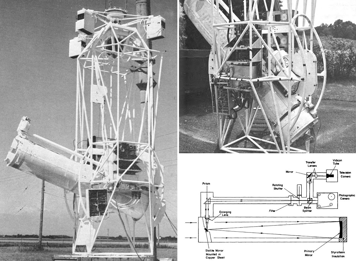
A scheme of the system flown in 1959 -an improved of the one flown in 1957- can be seen at left (click to enlarge). The telescope which was designed and constructed by the Perkin-Elmer Corporation, had an eight-foot long tube, at one end of which was a parabolic quartz mirror 12 inches in diameter. At the other end of the tube, a rotating plane mirror used in the first flights was replaced by a tiny fixed stellite mirror as a form to reduce the mechanical vibrations caused by the rotation. This mirror had an area of 2.0 x 2.8 mm and intercepted an area of 2.0 x 2.0 mm from the 23-mm diameter primary image of the sun. In order to prevent the stellite mirror from getting hot, it was mounted in a 2 mm thick copper sheet which extended across the 18-inch diameter of the tube. This sheet was fastened to the main tube in such a way as to make good thermal contact with the tube, thus providing sufficient heat conduction away from the stellite mirror that it did not heat up enough to cause serious optical disturbances. A prism reflected the light gathered by the stellite mirror back along a path above the tube of the telescope into a 35-millimeter motion-picture camera. A lens in the light path enlarged the image presented by the primary mirror to the size of an image that would be produced by a 200-foot telescope. At this magnification, each frame of the 35-millimeter film covered a rectangle about 50,000 by 35,000 miles on the surface of the sun. Exposures were made at a rate of one per second, each lasting a thousandth of a second. Another modification to the design after the 1957 flights was the introduction of a prism type beam's splitter behind the main shutter which divided the incoming image into two beams of equal intensity. One beam went directly through the beam's splitter to form an image on the photographic film, while the other beam was transmitted to a television camera to form an image on a vidicon tube.
But without doubt, the major upgrade made to the instrument was the addition of a television system which was developed specially for the project by the Radio Corporation of America. This system allowed the scientists to operate from the ground the focus of the telescope and also move the telescope in azimuth and elevation to select specific targets in the Sun. The circuits of the air-borne television camera were all transistorized while the television tube used was a one inch vidicon. The television vertical sweep was mechanically synchronized with the main shutter at a rate of one scan per second, but due to the fact that one scan would not completely erase an electrical image on the vidicon, it was necessary to add a second shutter between the beam-splitter and the vidicon. This shutter was synchronized with the main shutter in such a way that only every third image was allowed to fall on the vidicon.
Another modification introduced for the 1959 flight series was a very complex command and telemetry system which was constructed by Data Control Systems Inc.. The command channel enabled an operator in the ground station to increase or decrease the setting of six different controls by activating small DC motors in the telescope. These controls were telescope focus, azimuth position on the sun, elevation position on the sun, television black-level voltage, television target voltage, and one spare which was used to duplicate focus. On the other hand, the telemetry system transmitted sequentially 33 different values, such as temperatures, battery voltages, eye voltages, servo motor torques, elevation angle of the telescope, the relative azimuth angle of the telescope and the flywheel among others.
The guiding mechanism for the telescope was designed and built by the Research Service Laboratories of the University of Colorado. The telescope tube was mounted in a gimbal structure about 12 feet high on axes which permitted motion in elevation and azimuth. Small photosensitive cells searched out the sun and controlled the electric motors that moved the telescope. The instrument was aimed in azimuth by rotating the gimbal structure against the reaction of a 175-pound flywheel, and in elevation by rotating the tube against the reaction of the whole framework. At the top of the figure above can be seen the six four-volt automobile batteries distributed around the circumference which served as the weight for the flywheel and also as power to drive the pointing motors, the electronic controls, and the camera. The only modification made in the pointing system for the 1959 flight series was the replace of the continuously rotating motor at the top of the instrument by an AC servo system constructed also by the Perkin Elmer Corporation thus reducing further the mechanical vibration caused by the continuously rotating parts.
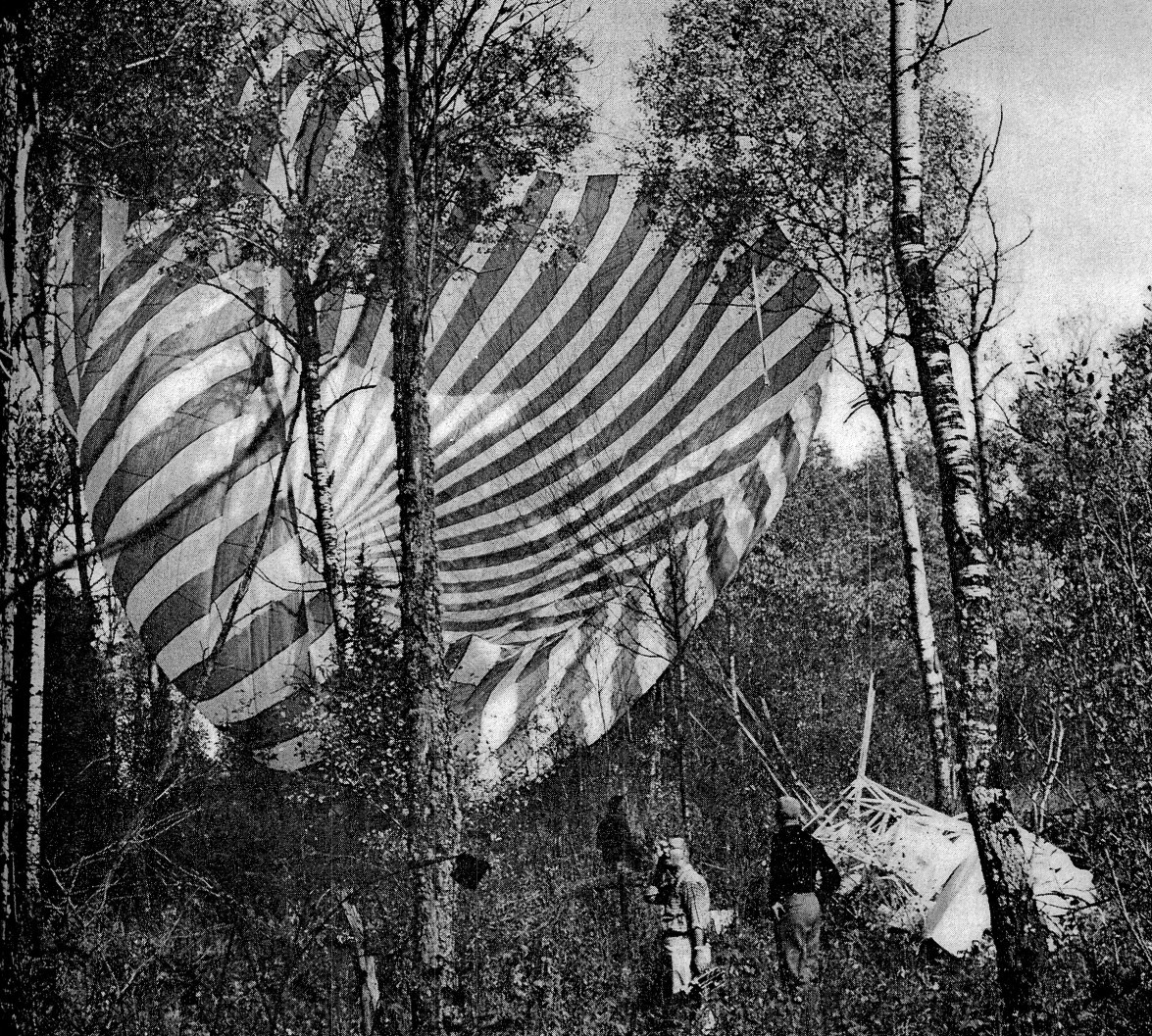
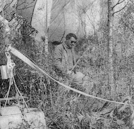
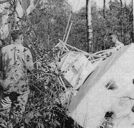
In flight the top part of the instrument was attached to a 90 feet long cargo parachute through a bearing located immediately above the flywheel, and the top part of the parachute was in turn attached to the bottom of the balloon. After the film in the camera was exhausted, a preset timer stowed the telescope vertically within the frame and cut down the parachute away from the balloon. In addition to serving as a mounting, the frame protected the telescope when it touched the ground: while a Styrofoam crash pad on the bottom abosrbed the impact of the landing, the flywheel at the top protected the telescope when the frame toppled over on its side.
The addition of the remote control and real time monitoring capabilities necessitated the addition of a mobile ground station. It was mounted in a 15-foot van on a standard truck, which housed the television, telemetry, and command equipment. The mobile station was powered by two 3,5-kilowatt, 115-volt AC generators transported in a 5x8 foot trailer. For receiving and transmitting were used Yagi antennas mounted on tripods 50 feet away from the van. A radio receiver and transmitter was also used by the balloon contractor to maintain communications between the ground station and the launch site, tracking center, or tracking aircraft.
Inside the ground station, four people were required to operate the Stratoscope at altitude. First, the astronomer, who sat facing a television monitor with a set of command controls to point the telescope to the desired portion of the sun's disk and to adjust the focus to the optimum setting. Second, a television operator, who sat facing a duplicate monitor with a duplicate set of command controls whose job was to point the television receiving antenna and to adjust the air-borne television camera and the monitors in the ground station so that the astronomer was presented the best possible picture. A third person monitored the telemetry system and the recorder, and marked on the strip-chart record all commands and operations performed by the astronomer and television operator. Finally, the fourth person, the navigator, computed for the astronomer the telemetry coordinates of selected regions on the sun.
Details of the balloon flight
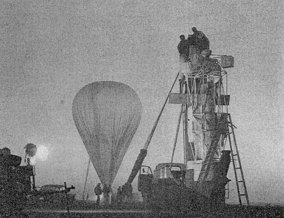
Balloon launched on: 9/24/1959 at 6:20 local
Launch site: Lake Elmo Airport, Minnesota, US
Balloon launched by: General Mills Inc.
Balloon manufacturer/size/composition: Zero Pressure Balloon
Flight identification number: GMI Nº 2442
End of flight (L for landing time, W for last contact, otherwise termination time): 9/24/1959 at 12:31 cdt
Balloon flight duration (F: time at float only, otherwise total flight time in d:days / h:hours or m:minutes - ): ~ 6 h
Landing site: 17 miles NE of Antigo, Winsconsin, US
Payload weight: 1690 lbs
This was the fourth and last launch of the 1959 Stratoscope series, dubbed as flight "D". It was launched by dynamic method from Lake Elmo Municipal Airport, Minnesota on September 24. However the operation was a partial failure as at release the Stratoscope collided with the superstructure of the launching truck and tore one of the main power batteries from the flywheel. This reduced the power available by half, but fortunately there was a safety factor of 2 in the available power. A more serious consequence of this was that the missing battery unbalanced the azimuth flywheel. This provided a coupling between the elevation and azimuth servo systems. It seems very likely that this caused the number of high-definition photographs in flight D to be much less than in B or C.
In flight D it was decided to replace the Kodak VG film used in the first three flights by Kodak Background X film. The purpose of this was to increase the sensitivity of the film, in order to photograph details in the sunspot umbras and near the sun's limb. However due to the mishap at launch, only a few high-definition photographs of sunspot umbras and of the limb were obtained.
This would be the last mission of the Stratoscope I system.
External references
- Of current interest: Television joins telescope in Stratoscope I balloon flights Electrical Engineering, Volume: 78, Issue: 10, Oct. 1959
- The structure of sunspots penumbras. I. Observations The Astrophysical Journal, Vol. 134 Nº 2, september 1961
Images of the mission
If you consider this website interesting or useful, you can help me to keep it up and running with a small donation to cover the operational costs. Just the equivalent of the price of a cup of coffee helps a lot.
