
Purpose of the flight and payload description

The Payload for Ultrahigh Energy Observations (PUEO) was a long-duration balloon-borne radio observatory designed to detect ultrahigh-energy neutrinos through Askaryan radio emission in Antarctic ice and radio signals from extensive air showers in the atmosphere. Developed as the successor to the ANITA program, it retained ANITA flight heritage while improving sensitivity, trigger threshold, collecting area, pointing accuracy, and radio-frequency interference rejection. PUEO was developed through a collaboration led by the University of Chicago, with major contributions from The Ohio State University, the University of Hawaii at Manoa, the University of Kansas, and numerous other institutions.
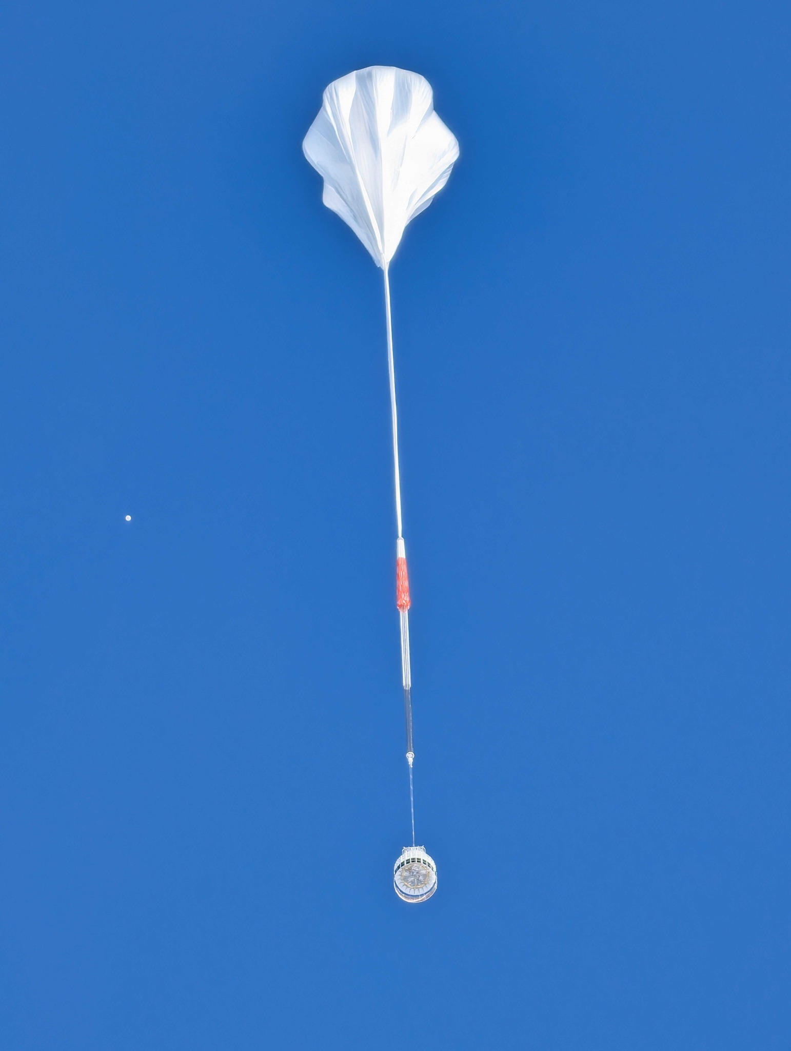
PUEO consisted of two complementary subsystems: the Main Instrument, operating from 300 to 1200 MHz, and a deployable Low Frequency (LF) instrument covering approximately 50300 MHz. Together they provided more than 200 radio channels distributed throughout the payload. In the image at left we can see an artistical representation of PUEO in flight.
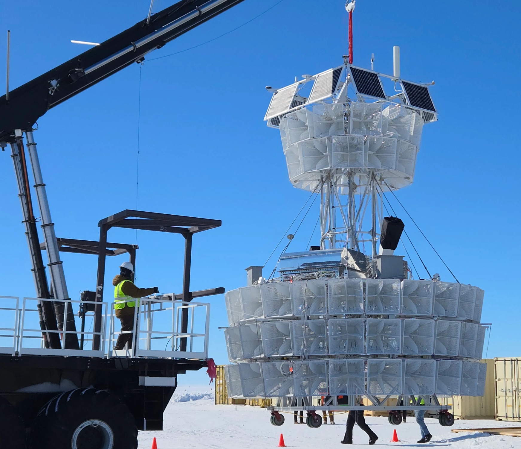
The Main Instrument used dual-polarized quad-ridged horn antennas designed for wide bandwidth, high gain, low reflection coefficient, and high polarization isolation. Each horn measured approximately 25 inches across the aperture and 27 inches deep and recorded both horizontal and vertical polarizations. Depending on the design stage, the payload carried 96 to 108 antennas arranged in four or five concentric rings. Twenty-four azimuthal sectors surrounded the gondola, each containing a vertical stack of antennas. Most antennas were pointed approximately 10° below the horizon to maximize sensitivity to signals emerging from Antarctic ice, while a deployable lower ring pointed about 40° downward to improve air-shower detection. The configuration provided full 360° azimuthal coverage and allowed impulsive signals to be observed simultaneously by multiple sectors.
Raising the low-frequency cutoff from the ANITA design to 300 MHz reduced antenna size while maintaining performance. This allowed roughly twice as many antennas to be installed, more than doubling the effective collecting area and improving sensitivity. The higher cutoff also reduced interference from satellite transmissions.
Each polarization channel was connected to an Antenna Mounted Pre-Amplifier (AMPA) module containing low-noise amplifiers and filters. These units provided approximately 60~70 dB of gain while contributing less than 80 K of noise temperature. A total of 192 amplification channels were enclosed in electromagnetic interference shielded housings to minimize self-generated interference. Signals were then routed to receiver boards for additional amplification, filtering, bias distribution, and signal conditioning. Radio-frequency-over-fiber links carried signals between the antennas and the central electronics enclosure. This architecture reduced cable mass, minimized signal loss, simplified wiring, and enabled a substantially larger channel count than previous balloon payloads.
A principal innovation was the interferometric phased-array trigger. Instead of triggering on individual antennas, the system coherently combined signals from multiple antennas after applying geometric delays corresponding to an incoming plane wave. This beamforming process increased signal-to-noise ratio by reinforcing coherent impulsive signals while suppressing uncorrelated thermal noise.
The trigger and data-acquisition system used Sampling Units for Radio Frequencies (SURF) based on Xilinx RFSoC technology. Each SURF digitized eight channels and performed real-time filtering, buffering, beamforming, polarization analysis, and trigger calculations. A central Trigger Unit for RF (TURF) synchronized all digitizers, distributed timing signals, coordinated trigger decisions, and transferred accepted events to the flight computer. The TURF also applied digital filtering to reject narrowband interference.
The Low Frequency instrument was deployed beneath the main payload after launch. It consisted of four dual-polarized antennas providing 8~16 channels, depending on configuration. The system was optimized for detecting radio emission from extensive air showers generated by cosmic rays or tau-lepton decays. Its lower operating frequencies improved air-shower sensitivity and enabled characterization of the Antarctic radio environment. The LF instrument incorporated an independent beamforming trigger, with trigger information shared between both subsystems so that either could initiate full-payload event recording.
All electronics were housed within a shielded Main Instrument Enclosure functioning as a Faraday cage with more than 80 dB of electromagnetic isolation. The enclosure contained receiver electronics, RFSoC digitizers, trigger hardware, the flight computer, data storage, telemetry systems, navigation equipment, and housekeeping electronics.
Event processing was performed by a Science Flight Computer based on an X-ES Xpedite7683 processor with GPU acceleration. The GPU executed real-time event prioritization and reconstruction. Events were approximately 0.5 MB in size and could be recorded at rates approaching 100 Hz. Data were stored in a triply redundant system exceeding 100 TB, sufficient for a month-long Antarctic flight. Telemetry links included TDRSS, Iridium, line-of-sight radio, and Starlink communications.
Navigation systems included differential GPS receivers, dual inertial measurement units, magnetometers, sun sensors, and star trackers. These systems provided attitude accuracy of approximately 0.05° and position accuracy better than 50 m, improving event localization and background rejection.
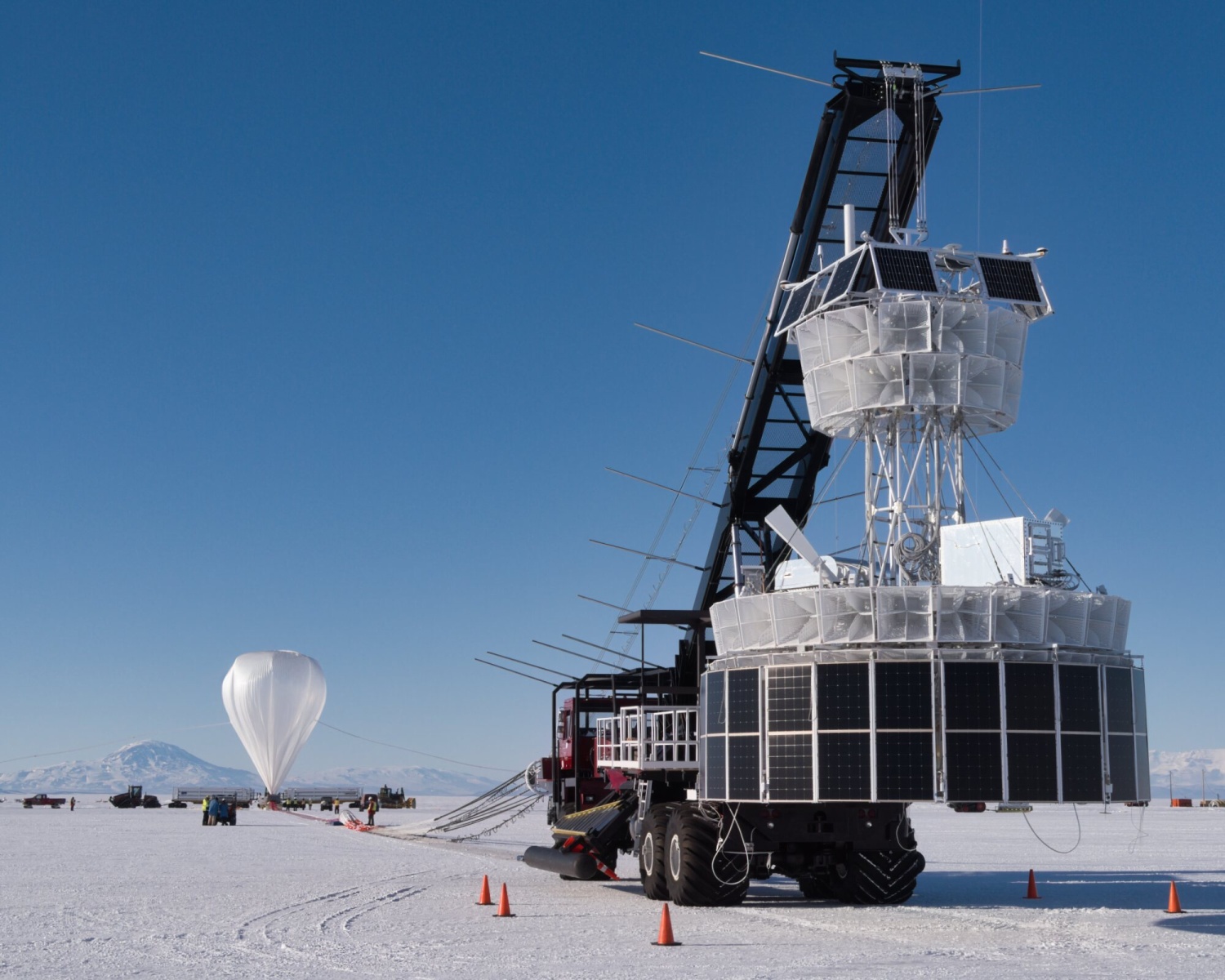
Power was supplied by rechargeable batteries operating on a 48 V bus and continuously recharged by a 24-sided omnidirectional solar array mounted beneath the antenna structure. The array generated approximately 1800 W, exceeding the payload demand of about 1250 W. Power-conversion units distributed regulated voltages throughout the instrument, while housekeeping systems monitored currents, voltages, temperatures, and subsystem status and could disable individual antenna sectors if required.
In-flight calibration was performed using ground transmitters and dedicated Hi-Cal balloon payloads launched several days after PUEO and following similar trajectories. These systems generated linearly polarized impulsive radio signals with selectable horizontal and vertical polarization states, enabling calibration of antenna response, timing synchronization, pointing accuracy, polarization reconstruction, and trigger performance throughout the mission.
Details of the balloon flight
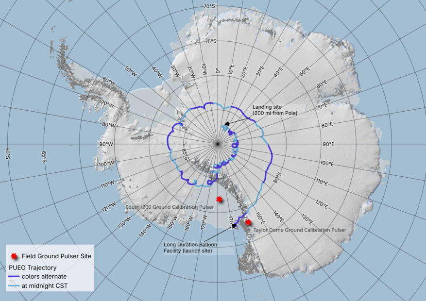
Balloon launched on: 12/19/2025 at 16:56 UTC
Launch site: Williams Field, McMurdo Station, Antarctica
Balloon launched by: Columbia Scientific Balloon Facility (CSBF)
Balloon manufacturer/size/composition: Zero Pressure Balloon
Flight identification number: 760N
End of flight (L for landing time, W for last contact, otherwise termination time): 1/12/2026 at 3:00 UTC (L)
Balloon flight duration (F: time at float only, otherwise total flight time in d:days / h:hours or m:minutes - ): 23 d 9 h 52 m
Landing site: In the East Antarctic Plateau, 255 km from the South Pole, Antarctica
External references
- PUEO website
- PUEO website NASA's HEASARC
- Design of the PUEO Payload Volume 470 - 10th International Workshop on Acoustic and Radio EeV Neutrino Detection Activities (ARENA2024) - Balloon-based radio experiments
- In Antarctica, balloon lands after 23-day search for particles from outer space University of Chicago website
- Modeling Neutrino and Background Signals for the Payload for Ultrahigh Energy Observations (PUEO) Experiment EPJ Web of Conferences 283, 06018 (2023)
- PUEO Prepares for flight in Antarctica University College London Website
- The Payload for Ultrahigh Energy Observations (PUEO): A White Paper Journal of Instrumentation, Volume 16, August 2021, p. 8035
- The Sensitivity of PUEO to Cosmogenic Neutrinos and Exotic Physics Scenarios ArXiv
- Trigger system for the Payload for Ultrahigh Energy Observations (PUEO) balloon-borne neutrino detector submitted to IEEE Transactions on Nuclear Science
- Two NASA Scientific Balloon Launches Planned From Antarctica NASA website
Images of the mission
If you consider this website interesting or useful, you can help me to keep it up and running with a small donation to cover the operational costs. Just the equivalent of the price of a cup of coffee helps a lot.