
Purpose of the flight and payload description
The General AntiParticle Spectrometer (GAPS) was an instrument designed to detect low-energy cosmic-ray antinuclei, particularly antideuterons, antiprotons, and antihelium, as indirect signatures of dark matter. Its primary goal was the detection of antideuterons below about 0.25 GeV per nucleon, where astrophysical backgrounds are expected to be very low and several dark matter models predict observable signals. Additional objectives included measurements of the low-energy antiproton spectrum, investigation of candidate antihelium events reported by other experiments, studies of cosmic-ray propagation and solar modulation, and demonstration of an alternative antiparticle-detection technique for future balloon and satellite missions. GAPS was developed by an international collaboration led by UCLA, with major contributions from Columbia University, the University of Hawaii, Caltech, the University of Maryland, the University of Tokyo, Waseda University, KEK, ISAS/JAXA, INFN laboratories, NASA balloon-program partners, Oak Ridge National Laboratory, and other institutions in the United States, Japan, Italy, and Europe.
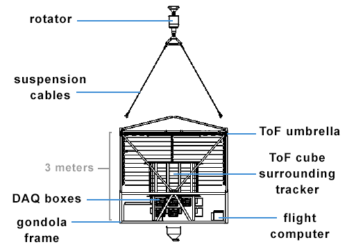
The instrument which can be seen schematically in the image at left (click to enlarge) was an antiparticle spectrometer composed by a Time-of-Flight (ToF) system, a silicon tracker, custom electronics, a thermal-control system, power and data-acquisition subsystems, and the gondola structure.
The outer detector was the Time-of-Flight system, which surrounded the tracker and provided the first stage of particle identification. It comprised two layers containing 160 plastic scintillator paddles read out by silicon photomultipliers (SiPMs). Charged particles produced scintillation light in the paddles, allowing measurements of velocity, trajectory, timing, and energy loss. The ToF system generated the primary event trigger and provided initial particle discrimination before particles entered the tracker. With more than 40 m² of active area, it supplied the timing precision required for velocity determination. Its measurements were combined with tracker data to identify antiparticles and reject backgrounds.
At the center of the instrument was the silicon tracker, which functioned as a stopping target, X-ray detector, particle tracker, and annihilation detector. Occupying about 2.5 m³, it contained 1,440 lithium-drifted silicon detectors arranged in ten layers. Each layer consisted of six rows of six detector modules. Seven layers were instrumented for readout, while three provided additional target mass and thermal balance. The tracker reconstructed particle trajectories, stopping points, annihilation vertices, and secondary-particle tracks. When an antiparticle stopped in the tracker, it formed an exotic atom in the silicon. Characteristic X-rays emitted during de-excitation and the subsequent annihilation products provided the main particle-identification signature.
Each tracker detector was a lithium-drifted silicon (Si(Li)) detector developed for GAPS. The detectors were fabricated from boron-doped silicon wafers 10 cm in diameter and 2.5 mm thick. Each detector was divided into eight strips surrounded by a guard ring. The strips provided position sensitivity, while the guard ring reduced surface leakage currents and preserved energy resolution. Operating between approximately -35 °C and -55 °C, the detectors achieved energy resolutions better than 4 keV in the 20100 keV X-ray range and better than 10% for ionization-energy measurements up to about 100 MeV. These characteristics enabled detection of exotic-atom X-rays while measuring energy deposited by charged particles and annihilation products.
Four Si(Li) detectors formed a detector module. Each module provided mechanical support, detector biasing, thermal coupling, and signal routing. Modules were mounted on lightweight antistatic polyethylene panels with cutouts to reduce passive material in the particle path. Heat-removal pipes passed through the tracker and connected the modules to the thermal-control system. Interface electronics around the tracker distributed power and transferred data to the acquisition system.
The tracker readout system used custom front-end electronics built around a 32-channel ASIC called SLIDER (Silicon Lithium Detector Readout), which processed signals from four detectors simultaneously. The system instrumented 11,520 silicon strips and accommodated energy deposits from about 20 keV to 50 MeV while maintaining the low noise required for X-ray spectroscopy. Each channel included a charge-sensitive amplifier, dynamic signal-compression circuitry, shaping amplifiers, comparators, sample-and-hold circuits, and analog-to-digital conversion. Detector signals were digitized and transmitted to the data-acquisition system for event reconstruction.
The power-distribution system supplied detector bias voltages and low-voltage power. Detector modules operated with reverse-bias voltages typically between 150 and 300 V. A network of 360 high-voltage channels and 60 low-voltage channels distributed power throughout the tracker. Embedded microcontrollers monitored and controlled power delivery through Ethernet-connected interfaces integrated into the data-acquisition architecture.
Detector performance required precise temperature control. GAPS used a thermal-control system based on oscillating capillary heat pipes. Heat generated by electronics and surrounding subsystems was transferred to heat pipes connected directly to detector modules. A two-phase working fluid carried heat to a radiator mounted on the gondola sidewall, where it was dissipated by thermal radiation. The system consisted of 36 interconnected capillary loops spanning all ten tracker layers and cooling all 360 detector modules. Fluid circulation relied on density differences between warm vapor and cooled liquid, eliminating the need for mechanical pumps.
The data-acquisition system served as the central control and readout architecture. Front-end ASICs communicated with FPGA-based back-end electronics. Each tracker plane was managed by a dedicated FPGA acquisition unit, while detector-module chains were controlled through SPI interfaces. The system synchronized detector readout, assembled tracker and ToF event data, distributed commands, monitored instrument health, and transferred scientific data to the flight computer for storage and telemetry.
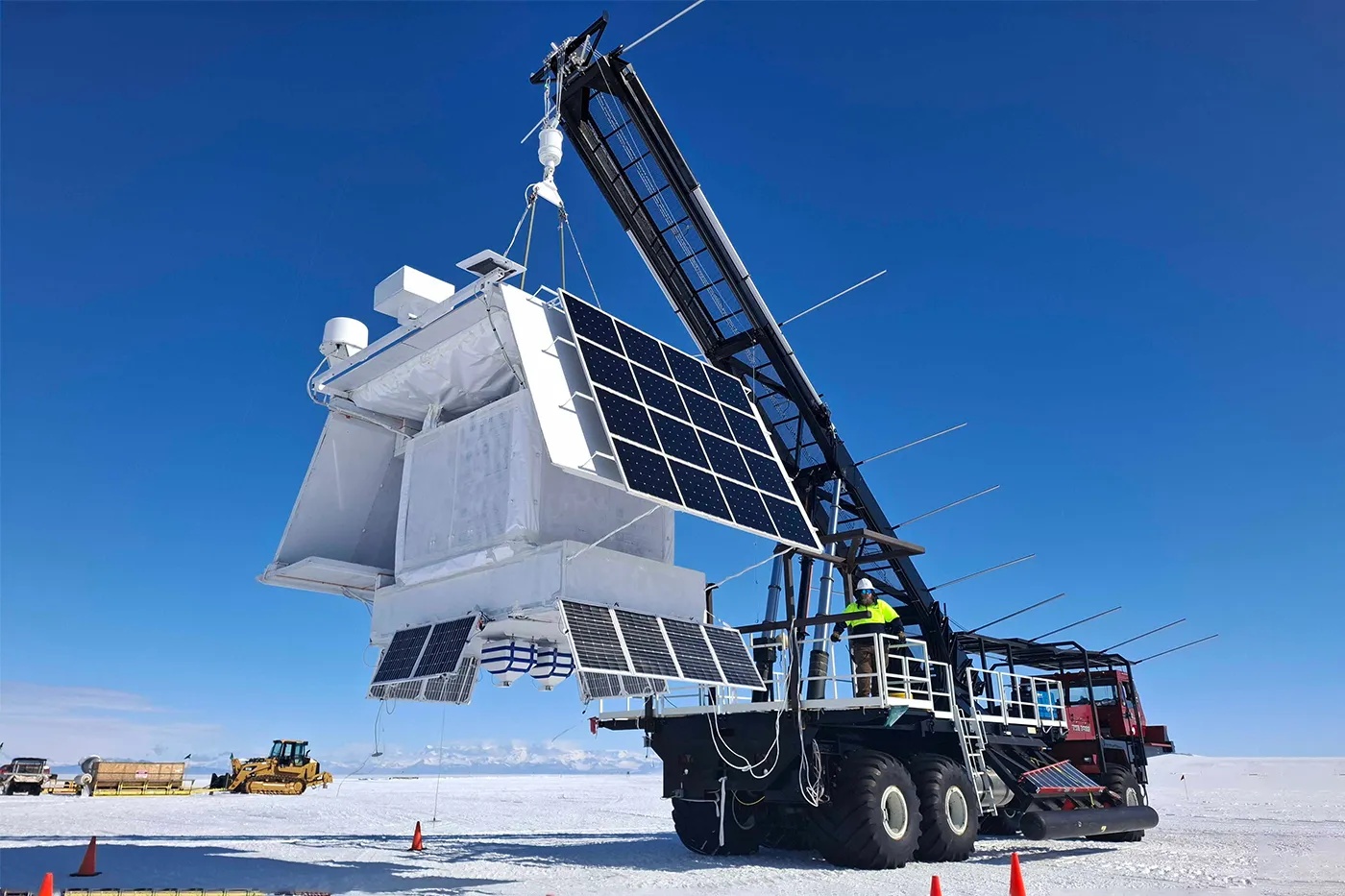
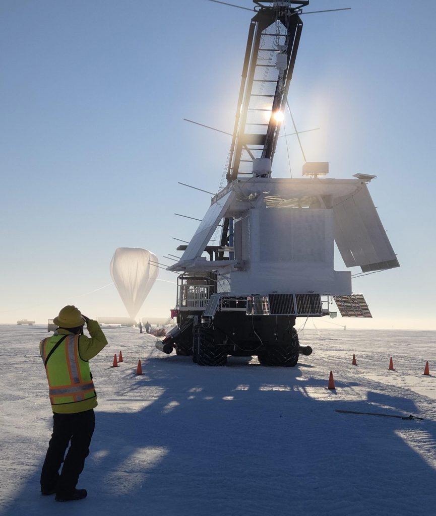
All subsystems were supported by a balloon gondola designed to withstand launch, flight, and landing loads. The gondola supported the tracker, ToF system, electronics, radiators, telemetry equipment, and solar-power infrastructure while maintaining detector alignment. Solar panels supplied electrical power during Antarctic flights, and telemetry systems transmitted housekeeping and scientific data to ground stations.
Details of the balloon flight
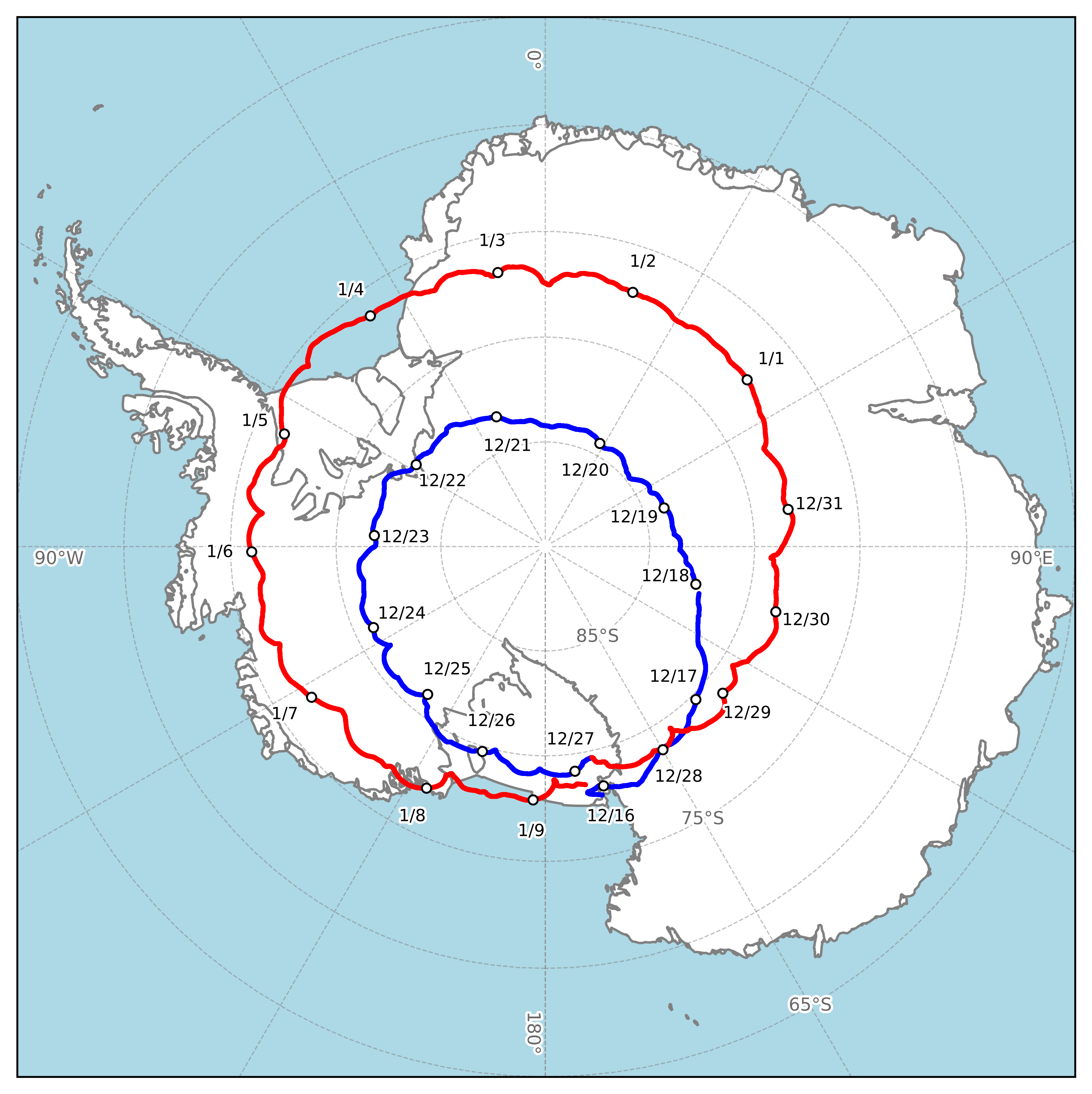
Balloon launched on: 12/15/2025 at 16:30 UTC
Launch site: Williams Field, McMurdo Station, Antarctica
Balloon launched by: Columbia Scientific Balloon Facility (CSBF)
Balloon manufacturer/size/composition: Zero Pressure Balloon
Flight identification number: 759N
End of flight (L for landing time, W for last contact, otherwise termination time): 1/9/2026 at 19:30 UTC
Balloon flight duration (F: time at float only, otherwise total flight time in d:days / h:hours or m:minutes - ): 25 d 2 h 53 m
Landing site: 60 km al SE de la Estacion McMurdo, Antartida
External references
- GAPS website JAXA
- GAPS website UCLA
- Completion of the first Antarctic balloon flight of the GAPS mission investigating cosmic-ray anti-particles JAXA website
- Concluso con successo il volo di GAPS, lesperimento sullantimateria ASI Website
- GAPS, a Balloon Experiment Pursuing Dark Matter, Launches in Antarctica Columbia University
- GAPS: The Balloon Borne Dark Matter Search Experiment ISAS Research Information Portal
- These researchers flew a particle detector above Antarctica, hoping to find evidence of mysterious matter Northeastern Global News
- Two NASA Scientific Balloon Launches Planned From Antarctica NASA website
Images of the mission
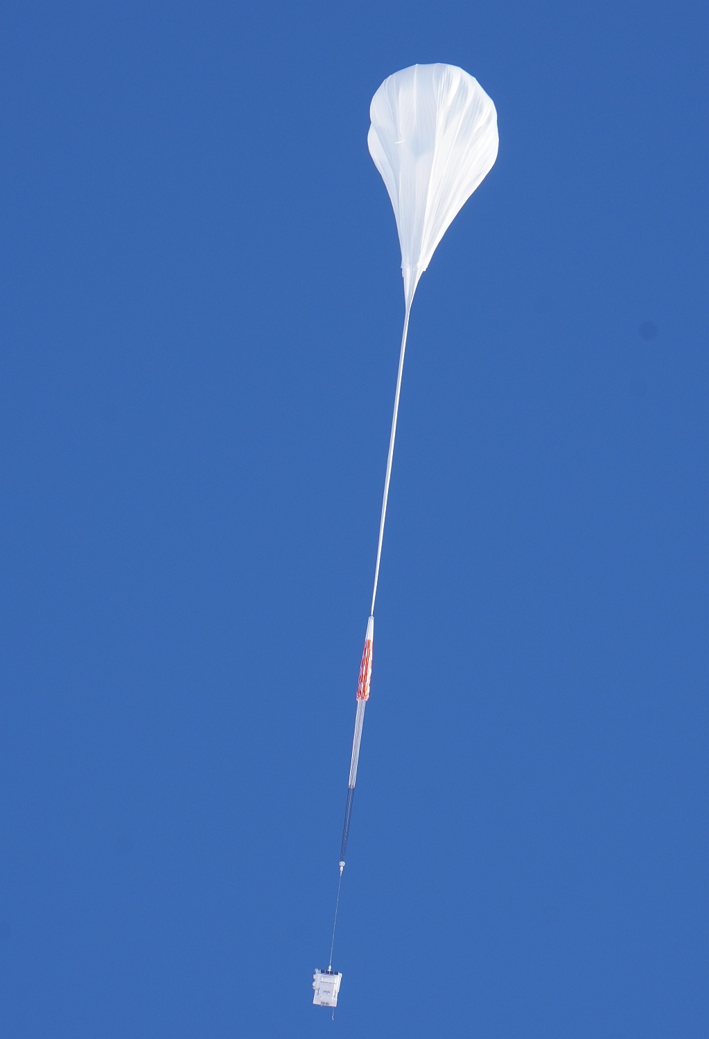
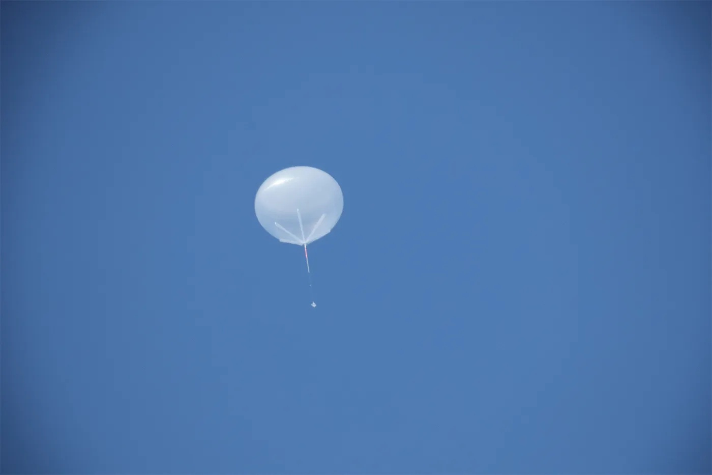
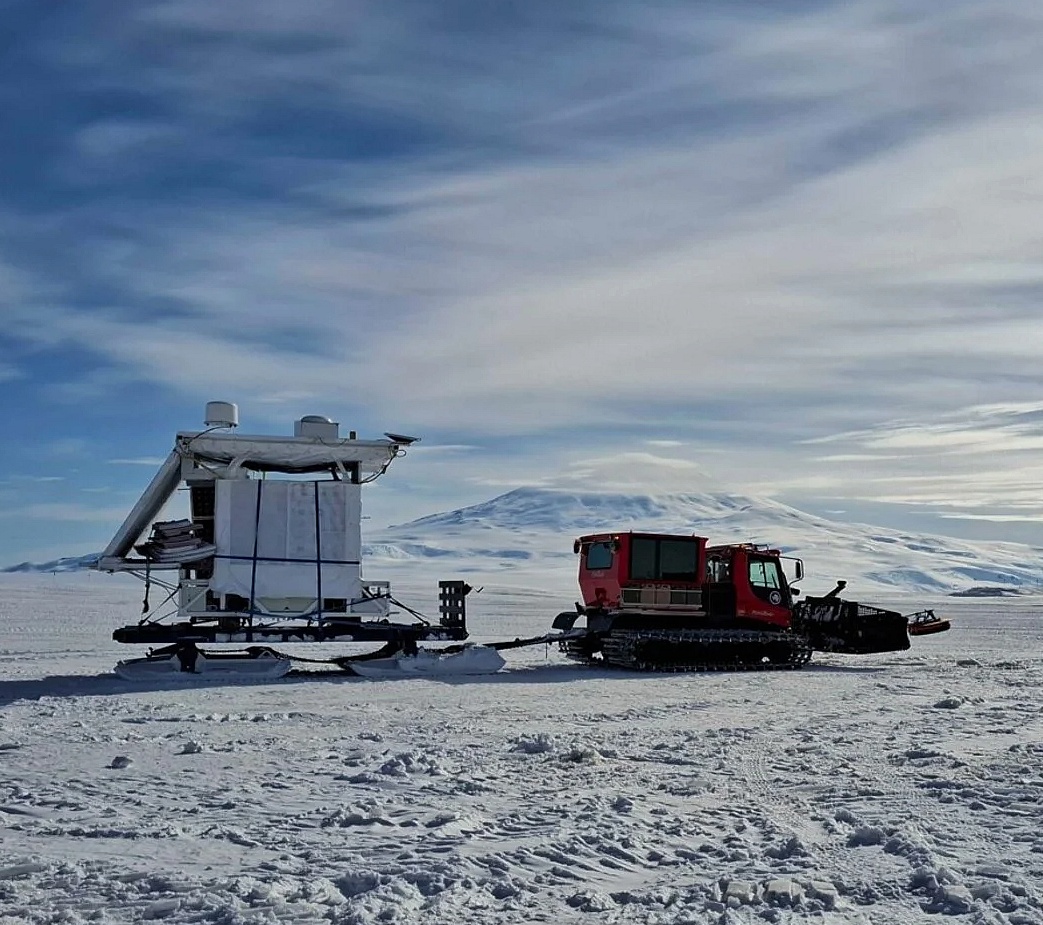
If you consider this website interesting or useful, you can help me to keep it up and running with a small donation to cover the operational costs. Just the equivalent of the price of a cup of coffee helps a lot.