Purpose of the flight and payload description
This test series was the first in a program of three test series designed to develop a new parachute system for Mars exploration as starting the new century, many of the lander missions under consideration included payloads that were five times more massive than those of previous missions. The program was carried out by the the Jet Propulsion laboratory, California Institute of Technology and Pioneer Aerospace with the support of NASA's National Scientific Balloon Facility.
The approach adopted instead of developing and qualifying a new system for these missions was to perform balloon-based drop tests of a 33.5 m Ringsail Canopy subsonic parachute to be used in conjunction with the existing supersonic Viking parachute as part of a two-stage system. The reason to use stratospheric balloons to tests this new design is based in the fact that in general, the atmospheric density near Mars surface is equivalent to Earth densities at altitudes between 30 and 35 km. The gondola plus canopy mass flown in these tests were 980 kg which corresponds to a Mars system mass of about 2500 kg.
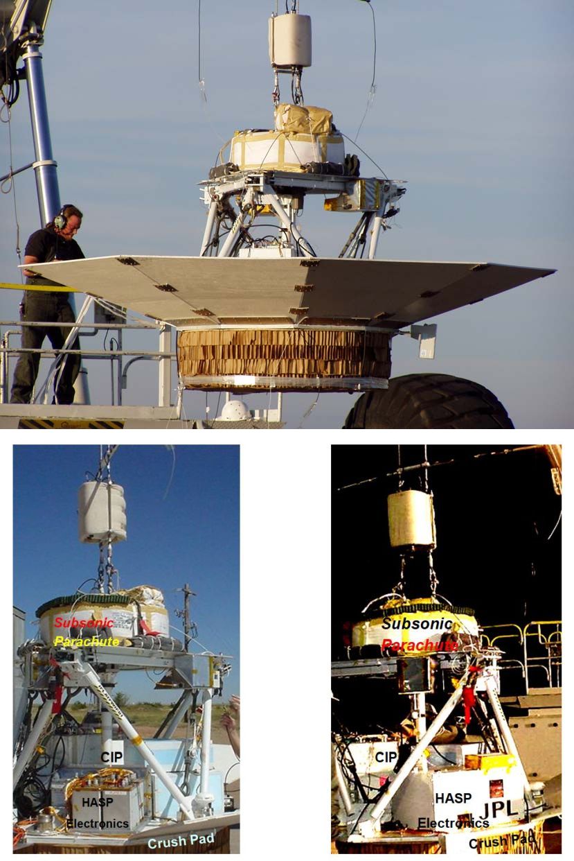
At left we can see an image of the gondola used for the tests (click for more details). It was a simple truss structure that included a faceted aerodynamic fairing to produce an aerodynamic wake similar to that expected from a hypersonic entry capsule of diameter of about 3.5 meters. The fairing assured the parachute inflated and operated in wake conditions similar to those expected on Mars. The structural base of the gondola was a 2.54 cm thick steel regular nonagon (a nine sided polygon with equal sides) with paper honeycomb crush pads mounted for ground impact energy absorption. On top of this base plate the batteries, instrumentation, pyrotechnics, and balloon telecommunications equipment were mounted. Bipod trusses connected the base plate to three structural nodes at the parachute deck above. Both the drogue triple risers and the main triple risers were attached to these structural nodes. The main ringsail canopy was stowed in an annular deployment bag on the parachute deck and the smaller drogue deployment bag was stored on top of the main. Staging of the main parachute was commanded by a pyrotechnics system on the Gondola. Cuting wires in the gondola released cutters activated timers in the on-board pyrotechnics system. When these timers expired, they commanded cutters at each structural node that simultaneously severed the three drogue triple risers.
The gondola carried four cameras: three up-looking cameras to observe the deployment and operation of the drogue and main canopies, one horizon looking camera, and one down-looking camera. The later was part of a separate experiment dedicated towards obtaining visual imagery for optical navigation of a pin-point landing technology task. Additional imagery was collected via a ground-based telescope fitted with a video camera and another video camera in the chase airplane.
The instrumentation suite included numerous sensors to record the deployment, inflation, and inflated performance of the parachute. All data was stored by an on-board, low power CPU with flash memory storage. The memory capacity (and Lithium-ion battery power supply) was sized for a 10 hour duration. This time accounted for potential delays in launch, or extended period at float while an acceptable descent corridor was found.
A Northrop Grumman LN-200 Inertial Measurement Unit included 3-axis accelerometers and 3-axis rate gyros for obtaining detailed data on gondola dynamics. Load cells were mounted in-line on each of the main parachute triple risers. In addition to providing a direct measurement of inflation loads, the load cells could describe the motion of the parachute relative to the gondola. A Global Positioning System (GPS) receiver and antennae were included to provide rough trajectory and altitude information. Five pressure transducers and numerous temperature transducers were also included.
Video of the parachute deployment
Details of the balloon flight
Balloon launched on: 10/25/2004 at 14:26 utc
Launch site: Scientific Flight Balloon Facility, Fort Sumner, (NM), US
Balloon launched by: National Scientific Balloon Facility (NSBF)
Balloon manufacturer/size/composition: Zero Pressure Balloon Winzen - 11.820.000 cuft (0.8 mil) - SF3-11-82-.8/.8-NAR
Balloon serial number: W11.82-1E-25
Flight identification number: 537N
End of flight (L for landing time, W for last contact, otherwise termination time): 10/25/2004 at 18:23 utc
Landing site: In SW Oklahoma, US
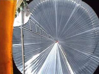
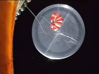
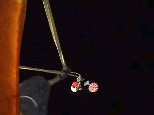
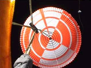
This was the fourth test in the series and the only partially succesful. The balloon was launched from the Scientific Flight Facility in Fort Sumner, New Mexico on October 25, 2004. Float altitudes winds were approximately 50 m/s to the East. The balloon achieved the desired float altitude in a location unsuitable for test conduct. The balloon drifted for 2 hours until it was east of Amarillo Texas and which time the test could be conducted with a safe landing in South Western Oklahoma. The test went as expected and the parachute inflated without damage as can be seen in the images at right and the video below.
Examination of the drogue's performance reveals an average drag area of 22.5 m2. At 20.95 seconds the gondola pyrotechnics circuit triggered main parachute deployment. Integration of this period indicates main deployment occurred at 167 m/s, Mach 0.54, and dynamic pressure of 148 Pa. Descent took just over 60 minutes and ended with a ground impact around 5 m/s. However, the uplook cameras revealed the reefing system did not work as expected. The reefing system was designed to constrict the canopy mouth to 15% of the parachute diameter for the first 6 seconds of inflation. This assisted in producing an orderly inflation and decreased the peak loads on the canopy. The video revealed that the reefing system was in place, and did hold the skirt in its proper configuration but there was no apparent pause in the inflation and the canopy went directly to its full inflation state. Fortunately, the canopy was designed with positive margin against a safety factor of two so that it possessed sufficient strength to handle the associated loads.
External references
- High Altitude Test Program for A Mars Subsonic Parachute 18th AIAA Aerodynamic Decelerator Systems Technology Conference and Seminar
Images of the mission

If you consider this website interesting or useful, you can help me to keep it up and running with a small donation to cover the operational costs. Just the equivalent of the price of a cup of coffee helps a lot.
