
Purpose of the flight and payload description
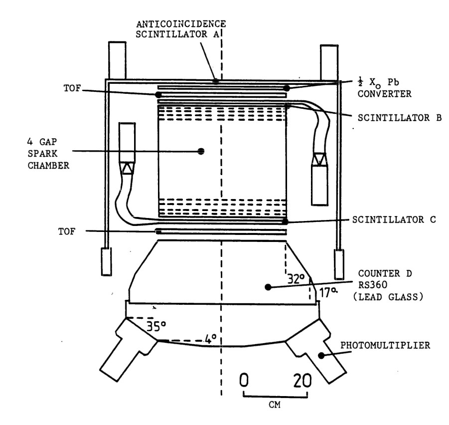
Objective of the flight was to detect Gamma Ray bursts with energies in the range of 50 KeV to 2 MeV using a gamma-ray telescope in a long duration balloon flight. The instrument developed by the Department of Physics of the Imperial College of Science and Technology in London was a pair-production instrument designed to investigate celestial gamma rays between 200 MeV and approximately 5 GeV.
The payload, which can be seen schematically in the image at left, combined a lead converter, coincidence scintillation counters, a time-of-flight system, a spark chamber, a lead-glass Cherenkov calorimeter, an anticoincidence shield, and an actively controlled pointing system. Its design emphasized efficient rejection of charged-particle background, accurate reconstruction of gamma-ray arrival directions, and measurement of photon energies over a wide field of view.
Incident gamma rays entered the detector through a circular lead converter 19 cm in radius and one-half radiation length thick. Pair production within the lead generated an electron and positron that traversed the detector. The converter thickness represented a compromise between maximizing pair-production probability and minimizing multiple Coulomb scattering, which degraded angular resolution and increased the probability that one secondary particle would escape before complete measurement.
Immediately below the converter were two circular coincidence detectors designated B and C. Both were fabricated from NE102A plastic scintillator with a radius of 19 cm. Detector B was 6 mm thick and detector C 12 mm thick. Each scintillator was viewed through polished Perspex light guides by a single EMI 6097A photomultiplier tube. Pulse-height information from both detectors was delayed electronically until a valid event was identified, after which the data were encoded for telemetry. These scintillators established the passage of the charged pair and formed part of the event-selection logic.
The trigger system required simultaneous signals from the coincidence scintillators, the Cherenkov calorimeter and the time-of-flight system, together with the absence of any signal from the anticoincidence shield. Only events satisfying this logic activated the spark chamber, reducing unnecessary operation and minimizing telemetry devoted to background events.
The time-of-flight system discriminated between downward-moving pair-production events and upward-moving secondary particles generated by cosmic-ray interactions within the calorimeter. It consisted of two NE104 plastic scintillators, each 20 cm in radius and 12 mm thick, separated by 50 cm. Each detector was viewed through optical light guides by two EMI 9810B photomultipliers positioned diametrically opposite. Fast leading-edge discriminators compared the arrival times of signals from the upper and lower scintillators. Because the available timing difference between downward- and upward-moving particles was approximately 3 ns, the electronics determined particle direction with an efficiency of about 90%, substantially reducing false triggers produced by backscattered particles.
Energy measurement was provided by a seven-radiation-length Cherenkov calorimeter constructed from Schott RS360 lead glass. Electromagnetic showers generated by the electron-positron pair produced Cherenkov radiation that was collected by six EMI 9530A photomultiplier tubes through Perspex light guides. The curved surfaces of the lead glass were polished and covered with reflective aluminium foil to improve light collection, while the upper surface was roughened and blackened to suppress light generated by upward-moving showers. Signals from the six photomultipliers were gain matched and summed before pulse-height analysis. The discriminator threshold corresponded to approximately 200 MeV, and the calorimeter provided energy measurements up to approximately 2.5 GeV.
Trajectory reconstruction was performed by a four-gap spark chamber positioned between the converter and the calorimeter. The chamber contained a gas mixture of approximately 31% helium and 69% neon. Each gap consisted of two orthogonal planes of copper-beryllium wires separated by 1 cm. Following a valid trigger, an 8 kV pulse was applied across the wire planes, producing sparks along the ionized paths of the electron and positron. Track coordinates were determined by a magnetostrictive readout system in which stress waves generated at the fired wires propagated along Permendur sensing wires to pickup coils located at both ends. Pulse arrival times were measured using a crystal-controlled 2.15 MHz clock derived from a 4.3 MHz oscillator, allowing reconstruction of particle trajectories and determination of the incident gamma-ray direction. The electronics were capable of resolving separate electron and positron tracks when sufficient spatial separation existed.
Charged particles entering through the sides or top of the telescope were rejected by an anticoincidence shield fabricated from NE102A plastic scintillator. The shield consisted of four cylindrical side panels, each 51 cm deep and 6 mm thick, together with a circular upper detector 38 cm in radius and 9.5 mm thick. The side panels were viewed individually by EMI 9524A photomultipliers, while the upper detector was viewed by two EMI 6097A photomultipliers. Any signal from the shield vetoed the event before spark chamber activation.
The payload incorporated a two-axis pointing system providing independent zenith and azimuth motion. Telescope orientation could be controlled automatically to track predetermined celestial coordinates or manually through telemetry commands transmitted from the ground. Attitude sensors continuously measured payload orientation, allowing reconstruction of the telescope pointing direction and assignment of celestial coordinates to every recorded event.
Detector electronics included high-voltage supplies, coincidence logic, pulse-height analyzers, spark chamber timing electronics, telemetry formatting circuits and event encoding hardware. Spark chamber coordinates, detector pulse heights, timing information and attitude data were assembled into telemetry words for transmission to the ground.
Details of the balloon flight
Balloon launched on: 11/16/1977
Launch site: Australian Balloon Launching Station, Alice Springs, Australia
Balloon launched by: ABLS
Balloon manufacturer/size/composition: Zero Pressure Balloon
End of flight (L for landing time, W for last contact, otherwise termination time): 11/17/1977
Balloon flight duration (F: time at float only, otherwise total flight time in d:days / h:hours or m:minutes - ): 30 h
The array was launched on a stratospheric balloon from Alice Springs, Australia on November 2 1977. Good data was obtained between 22:15 UTC 2 November 1977, and 08:15 UTC on 3 November 1977, however no burst were detected during that period.
External references
- Balloon-borne gamma ray astronomy and sources between 200 MeV and 5000 MeV Ph.D. Thesis by Hughes, J. B., Imperial College London, 1984
- Gamma ray observations in the energy range 0.3 J. Phys. E: Sci. Instrum. 15, 462 (1982)
- Gamma-ray burst measurements with a 6.3 sq M array Astrophysics and Space Science, vol. 77, no. 1, June 1981, p. 201
If you consider this website interesting or useful, you can help me to keep it up and running with a small donation to cover the operational costs. Just the equivalent of the price of a cup of coffee helps a lot.