Purpose of the flight and payload description
The payload used on this flight was a cryogenic whole air sampler for use in balloon-borne platforms in the lower stratosphere. It was part of a program started in 1974 by the Air Force Cambridge Research Laboratories (AFCRL) for stratospheric composition studies based on the interest of the US Air Force in the determination of any environmental effects due to the operation of high altitude aircraft like the B-1 or the F-15. The program goal was to measure, first , the natural or baseline levels of the minor species with impact in the atmosphere (CO, H2O, CFCL3, CFCL2 and other hydrocarbons) and then their variations in time and space as Air Force stratospheric operations expanded.
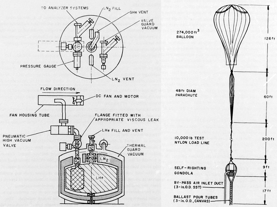
The flight train configuration can be seen at left. Clicking on the image a more detailed design of the sampler is shown. The sampler collected one mole of gas through a viscous leak in approximately one hour, by condensation on the cold wall. The total cryogenic hold time of the sampler was 20 hours using liquid helium. As a required industry safety feature, a fracturable metal diaphragm was connected to the sample container. The particular diaphragm utilized ruptures when the interior pressure rised above 18 psia, saving the internal parts from damage if the sample should be inadvertently warmed.
The sampler cylinder was surrounded by the primary cryogen which was surrounded with a portion of the thermal guard vacuum, then a liquid nitrogen heat shield, then another section of the guard vacuum, and finally the external wall. Precautions were taken to ensure the integrity of the gas collected, for example, gold plating on most of the interior surface, pre-flight evacuation to low pressure while heating to over 350°C, and so forth. The viscous leak was welded to a double sided vacuum flange, allowing it to be changed for various sampling altitudes. The leak used at 20 km was an 18.4-cm long tube with an inside diameter of 0.15 cm and the leak rate of ambient air through this tube was predicted to be approximately 7.4 standard cm3 of gas per second, allowing one mole to be collected in 50.4 minutes. The flow of air through the leak was turned on or off with a remotely commanded, pneumatically operated, high-vacuum valve fitted with a magnetically latching DC solenoid and using compressed helium as the working gas.
The gondola that housed the sampler was a estructure specially designed to be of high strengt. It was built using one-inch aluminum tubing. It was spherical -except for the base- and had a diameter of 87 inches. This design was intended to make he gondola self righting. To remove any possibility of the gondola becoming entangled in the load line or being dragged by the parachute, it was equipped with four impact switches that, upon landing, fired a pair of squibs that cutted away the load line and control cable. Also attached to the gondola were two aluminum ballast hoppers. Both hoppers were fitted with blow ports to allow complete dumping of any remaining ballast at flight termination. Each hopper was fitted with a 20-ft cloth tube, and the tubes were joined below the gondola. These tubes were added to reduce the possibility of any ballast being ingested by the sampling system.
The gondola was attached to the bottom of the parachute by a 200-ft length of 10,000-lb test nylon load line. The long line was to ensure isolation of the sampler from any surface contaminants on the balloon or parachute. The load line was deployed at launch to eliminate any problems that would be associated with reel-down systems.
Mounted within the protective frame of the gondola was the sampler already described, the pneumatic supply and control, and the sample intake system. The sampler was placed in a styrofoam box (2 Inches thick) to reduce the shock loading at impact and to ease handling before launch. The sampler and box were covered by a plastic sheet to minimize both the condensation which formed on the cryogen vents and the outgassing from the foam that could affect the integrity of the sample. Five 2-inches, nylon straps were used to secure the sampler to the frame.
The sample intake assembly consisted of two joined 10-ft lengths of 3-inches of flexible stainless-steel tubing, a small DC fan moving approximately 40 cuft of air per minute, and a stainless-steel fan housing tube where the air was diverted to the vacuum valve. The inlet for the flexible tubing hung below the gondola approximately 17 ft. This tubing was tied to the frame to reduce any damage resulting from a pull on the tubing. Before the flight, the tube was flushed with helium gas for 18 to 36 hours to reduce surface contamination effects.
Details of the balloon flight
Balloon launched on: 6/26/1975 at 7:15 pdt
Launch site: Chico Municipal Airport, California, US
Balloon launched by: Air Force Cambridge Research Laboratories (AFCRL)
Balloon manufacturer/size/composition: Zero Pressure Balloon 274.000 cubic feet
Flight identification number: C75-11
End of flight (L for landing time, W for last contact, otherwise termination time): 6/26/1975
This second flight of the instrument took place on 26 June, 1975 from Chico, California. The balloon was launched at 7:15 PDT and ascended towards the east, reaching float altitude in 75 minutes. The specified descent rate of 20 ft/min was achieved by valving and ballasting and the 50 minute sampling period was completed by 10:00 PDT. Following sampling, the balloon was directed to the northern end of the Sacramento Valley where the terrain was much more suited for a smooth landing and recovery. Termination and parachute descent were normal and, upon impact, the package rolled several times down an incline, landing in an upright position against a tree. The package was recovered 35 minutes later undamaged and with the sample intact.
External references
- Cryogenic, Whole-Air Sampler and Program for Stratospheric Composition Studies Environmental research papers series Nº 754 (1976)
- Stratospheric Composition Measurements Report on Research at AFGL July 1974 - June 1976, Pag. 26
- Stratospheric Trace Gas Composition Studies Utilizing in situ Cryogenic, Whole-Air Sampling Methods Environmental research papers Nº 732, March 1981
If you consider this website interesting or useful, you can help me to keep it up and running with a small donation to cover the operational costs. Just the equivalent of the price of a cup of coffee helps a lot.
