Purpose of the flight and payload description
The High Energy Gamma Ray Gas Cerenkov Telescope was born as a initiative of the Laboratory of Nuclear Studies at Cornell University in late 60's. That group started the project taking account that the detection of gamma rays from spatial sources is specially complicated due to several factors: the very low flux values to be obtained, the presence of a diffuse background of these rays coming from all directions, and a much larger background flux of charged particles. Therefore, the basic premises for a good detector required a combination of large detection area, long exposure time, high efficiency, good angular resolution, excellent background rejection, and simple data recording. With all this in mind the Cornell group started the development of a instrument that used a large tube filled with an appropriate gas, capped at one end by a scintillator-lead-scintillator sandwich and at the other by a scintillator and a mirror that focused the Cerenkov light on a small array of photomultiplier tubes. First steps were carried with support from the Air Force Office of Scientific Research (AFOSR) while temporary collaboration was arranged with the Smithsonian Astrophysical Observatory, who designed the orientation system. In November, 1970, AFOSR retired from the project for lack of military relevancy, but at the same time NASA started its involvement on it providing the neccesary grants to complete the instrument development and to perform the balloon flights.
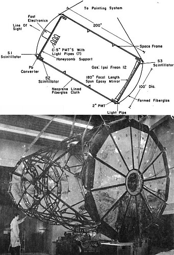
The instrument was formed by a big cilinder measuring 100 inches of diameter and 200 inches of longitude. As one single mirror of such diameter was at the time difficult to handle and costly to manufacture, the telescope mirror was constructed from 19 hexagons coated with aluminum and cut on the outer edge to match the shape of the 12 sided scintillator array. The mechanical structure consisted of two molded fiberglas heads joined to a neoprene lined, fiberglas cloth bag by means of two bolt rings. The neoprene, provided a light tight, gas tight bag as well the fiberglas heads which was also lined with neoprene. The aluminum space frame shown in the scheme above connected the two heads. This framework fixed the phototubes at the focus of the mirror and relieved the longitudinal forces on the bag when it was pressurized. Two aluminum honeycomb pallets were coupled to the heads and the space frame supporting the scintillators, lead, mirror, and electronics.
To facilitate the emission of Cerenkov radiation by the particles that traversed the telescope, the interior of the cilinder was filled with an equal mixture of Freon-12 gas and air. A system consisting of several switches and a large poppet valve, allowed the regulation of the pressure while the balloon ascended until it reached the optimal value of 1.6 psia at float altitude.
The three scintillators, S1, S2 and S3 were each divided into 12 symmetrical sectors one quarter inch thick and viewed from the outermost edge by a phototube through a light pipe made from eight strips of plexiglass. The Cerenkov detector was composed by a five-inch Bi-Alkali photomultiplier tube, while to collect the light at the mirror focus seven phototubes with light funnels of eight inch diameter were used.
An advantage of this detector was that because of its size, time delayed coincidences were be used to reject particles traveling in the wrong direction. The fast electronics required for this were constructed from MCEL logic cards. The outputs from the Sl, S2, S3 and Cerenkov phototubes were separately mixed by linear fan-ins. The multiplexer consisted basically of six sixteen pole switches. The information from each event, along with time parameters and housekeeping data, were recorded on a seven track digital magnetic tape recorder, and were also telemetered to ground.
The orientation system, permited to control the zenith angle of the telescope from the ground by commanding the drawing of a wire rope over a capstan. The desired angle was obtained by seting the offset of a magnetometer with respect to the lift bar on which it was mounted. Also the whole payload rotated through a thrust bearing, turning against a multifilar suspension and the inertia of the balloon, until the offset magnetometer achieved a null reading. Supplementary orientation information was provided by other magnetometers, a shaft encoder attached to the axis of a pendulum, a sun-seeker, and by a camera oriented along the telescope axis to photograph the brighter stars.
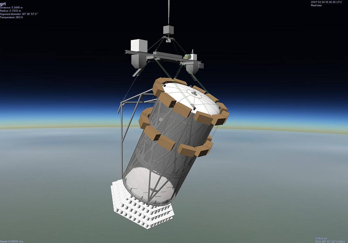
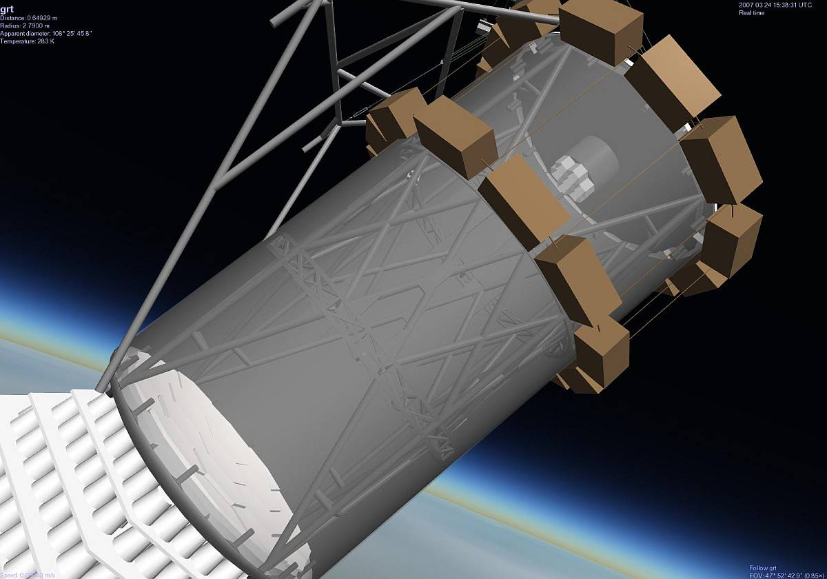
The external estructure of the instrument was protected by two crush pad systems: one formed by several layers of styrofoam cups placed under the bottom head and the other consisting of two rings of cardboard honeycomb placed around the outside near the top. This allowed to protect the instrument at landing even if the telescope toppled over. The weight of the telescope, without crush pad and pointing-system, was 2.600 lbs and the total weight of the scientific package was 3.400 lbs.
Details of the balloon flight
Balloon launched on: 2/18/1972
Launch site: Columbia Scientific Balloon Facility, Palestine, Texas, US
Balloon launched by: NCAR National Scientific Balloon Flight Station
Balloon manufacturer/size/composition: Zero Pressure Balloon Winzen - 20.800.000 cuft (0.8 mil) 2x 0.9 mil caps + reefing sleeve
Balloon serial number: SF 375.08-080-NSC 02 - Serial Nº 10
Flight identification number: 661P
End of flight (L for landing time, W for last contact, otherwise termination time): 2/18/1971
Balloon flight duration (F: time at float only, otherwise total flight time in d:days / h:hours or m:minutes - ): ~ 1 h
Landing site: Balloon failure at 51.700 ft
Payload weight: 4471 lb
This was the third flight of the instrument but no scientific data was obtained due to the balloon failure.
External references
- Balloon Flight Record Nº 42 National Center for Atmospheric Research, Spring 1972
- Cosmic Gamma-Ray Telescope Final Technical Report, 1 Nov. 1970 - 28 Feb. 1976
- Digital model of the Gas-Cherenkov Gamma-Ray Telescope for Celestia Space simulator at Selden Ball's home page
- National Scientific Balloon Facility Annual Report FY 1973 National Center for Atmospheric Research, September 1973
- Flight Summary of balloons made of Stratofilm - 1971 to 1972, Technical report, Winzen Research International. Circa 1973 - Stratocat's private collection
- Review of Recent Performance of Large Balloons and Balloons with Payloads in Excess of 3000 Pounds Proceedings, Seventh AFCRL Scientific Balloon Symposium, 1973
2503If you consider this website interesting or useful, you can help me to keep it up and running with a small donation to cover the operational costs. Just the equivalent of the price of a cup of coffee helps a lot.


