Purpose of the flight and payload description
This balloon mission was part of a series carried out in Rome in the second half of 1962 aimed to measure cosmic-ray intensity profiles at mid-latitudes under both quiet and disturbed geomagnetic conditions. They also sought to detect delayed solar protons after flares and investigate unexpected radiation increases, which were later linked to radioactive debris from nuclear tests. The program was carried out by the Istituto di Fisica dell'Universitá di Roma and the Commissione Italiana per le Ricerche Spaziali del CNR.
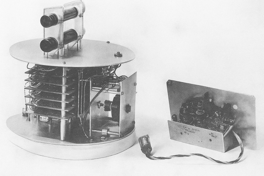
In the image at left we can see a picture of the standard payload. It was composed by radiation detectors, pressure and temperature gauges, electronic processing circuitry, and a telemetry system. The entire setup was enclosed in a black-painted aluminum container approximately 0.5 mm thick with a foam shell about 5 cm thick, which helped maintain a stable internal temperature. The detectors, gauges, and electronics were mounted on a lightweight aluminum frame, with high-voltage circuitry encased in araldite to avoid electrical discharges at low ambient pressures.
The flight train consisted of the balloon itself, a parachute, a container with safety devices, the instrumented payload, a power supply, and a coaxial dipole transmitting antenna at the bottom. The radiation detectors included various Geiger-Müller counters, such as Anton 316, Ital-Elettronica GM15D, Victoreen 1B85, and on one occasion, a small-area Anton 302. In most flights, two or three horizontal Geiger counters (A, B, C) were placed in a vertical plane, spaced 4 cm apart. Measurements included single counting rates and twofold coincidences (AB or BC). Some counters were shielded with copper or aluminum absorbers of known thickness.
Pressure was measured with an aneroid-based oscillator circuit whose frequency varied with altitude, allowing remote tracking via telemetry. Temperature near the detectors was monitored by a thermistor whose signal also modulated a telemetry channel and was periodically calibrated in flight.
The output circuitry was designed to ensure reliable telemetry over distances greater than 300 km. Detector pulses were converted into low-frequency variations of d.c. levels that modulated subcarrier frequencies. A control circuit monitored the count rate and, if it exceeded a set threshold, redirected the signal to a secondary scaler and used a high-voltage sensing circuit to check for spurious discharges. This sensing system included a corona tube in series with a subcarrier oscillator input, producing a modulation current proportional to the high-voltage drop across the tube, allowing sensitivity to voltage changes as small as 50 V.
Telemetry transmission was handled by an 18-channel FM-FM system operating at 136.5 MHz, built by Contraves Italiana. Four channels typically carried detector outputs, while the full bandwidth of channels 17 and 18 was used for pressure data. A 10-element Yagi antenna mounted on a 12-meter tower received the signals, which were recorded on low-speed pen recorders.
Safety mechanisms included a parachute and two release systems: one remotely triggered from the ground, and an automatic system that activated if the balloon descended below 13 km or after a preset flight duration of about 8 hours.
Details of the balloon flight
Balloon launched on: 11/23/1962 at
Launch site: Rome Italy
Balloon manufacturer/size/composition: Zero Pressure Balloon
End of flight (L for landing time, W for last contact, otherwise termination time): 11/23/1962
Balloon flight duration (F: time at float only, otherwise total flight time in d:days / h:hours or m:minutes - ): 2 h
External references
- Balloon measurements of cosmic rays and radioactive debris near rome in 1962 Il Nuovo Cimento Series 10, 1 Giugno 1965, Volume 37, Issue 3, pp 793-817
If you consider this website interesting or useful, you can help me to keep it up and running with a small donation to cover the operational costs. Just the equivalent of the price of a cup of coffee helps a lot.
