Purpose of the flight and payload description
Project FAR SIDE was an experimental United States Air Force research effort conducted in 1956-1957 under the Air Force Office of Scientific Researchs Directorate of Advanced Studies, intended to probe the upper atmosphere and near-space environment using balloon-launched, multi-stage rockets. It was conceived in the context of growing Cold War interest in space and the Air Forces desire to remain a central actor in space research.
FAR SIDE adopted an unconventional and relatively inexpensive approach: a large helium balloon would lift a multi-stage rocket to altitudes of roughly 80,000-100,000 feet, from which it would be fired to reach distances of up to several thousand miles, carrying instruments to measure cosmic radiation and the Earths magnetic field. Since early 50's the so called Rockoon technique (contraption of ROCKet and ballOON) was used by several scientific groups that fired single-stage research rockets from stratospheric balloons launched from small vessels. However, the scale and complexity proposed by Far Side was a leap forward of several orders of magnitude.
Aeronutronic Systems, Inc., a subsidiary of the Ford Motor Company, served as the prime contractor for the rocket , General Mills designed and provided the massive polyethylene balloons while the University of Maryland was responsible for the scientific instrumentation onboard.
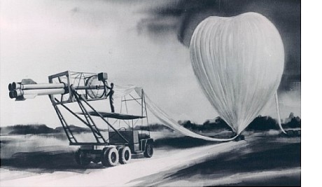
In the scheme at left we can see a detailed view of the entire launch system before flight (click for more details and diagrams)
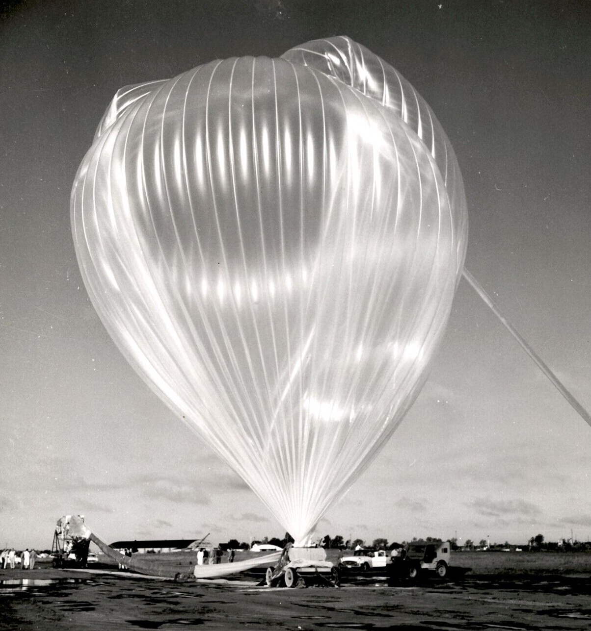
The Balloon was a 3,750,000 cubic foot gas bag made of 2-mil polyethylene, designed and built by the Mechanical Division of General Mills to lift the 2,000-pound Far Side vehicle to 100,000 feet. The balloon weighed 1,500 pounds, measured 303 feet in length when slack, and had an inflated diameter of 204 feet. Its structure consisted of 80 panels with welded fortisan load tapes. At the top, the tapes were connected to a nylon rope forming a 7-foot-diameter window. At the bottom, the tapes were fitted with clips to attach to the rocket launchers load ring. The window design replaced a metal sealing device and allowed the vehicle to exit through the apex of the balloon when fired.
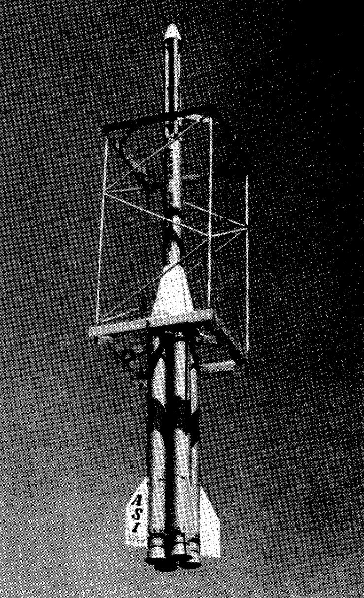
The Rocket launcher was a key component of the system. As the Far Side rocket was meant to be fired through the balloon, a light-weight aluminum box-type structure, consisting of a balloon load attachment ring at the forward end and a zero length launcher platform at the aft end, provided the means of handling and launching of the Far Side rocket. Launching arms pivoted from the box-type frame held the vehicle when in the near horizontal position during balloon inflation and launching operations, and in the vertical position during the balloon ascent. When fired, the launch arms were flipped clear of the frame by the forward motion of the vehicle, thereby preventing contact between the arms and the vehicle proper. For safety purposes, the forward end of the vehicle was positioned by means of a special harness during handling and launching. The launch arm safety wires and the harness were removed by electrically fired cable cutters prior to actual firing of the first stage rocket engines.
Balloon instrumentation was mounted on the launcher structure and comprised three main components. First, a crystal-controlled radio command receiver with resonant reed relays activated the rocket engine ignition circuits. Second, a baro-transmitter transmitted altitude data during ascent and signaled the proper functioning of the radio receiver through a coded pressure signal. Third, an electric timer armed the firing circuit and served as a backup safety mechanism in case the radio command receiver failed.
The Far Side rocket was a four stage vector: first stage was powered by four solid propellant Recruit rocket engines supplied by the Thiokol Chemical Corporation; the second stage was a single Recruit engine; the third stage was a cluster of four Arrow II solid propellant rocket engines made by the Grand Central Rocket Co.; and the fourth stage, to which the instrument package was attached, was a single Arrow II rocket engine located within the third stage cluster. Overall length was 24 ft, gross weight at launch was 1.970 lbs, and the maximum velocity attained was 26.000 feet per second. Peak expected altitude was 4.060 miles.
On this flight, however, instead of the real rocket a same-size and weight mockup was transported and tested under near-operational conditions as the balloon mission was conducted as a full-scale flight test for the FAR SIDE program. Goal was to evaluate the performance of the polyethylene balloon system built for the project, its associated suspension and launch hardware.
Details of the balloon flight
Balloon launched on: 6/28/1957 at 8:03 cdt
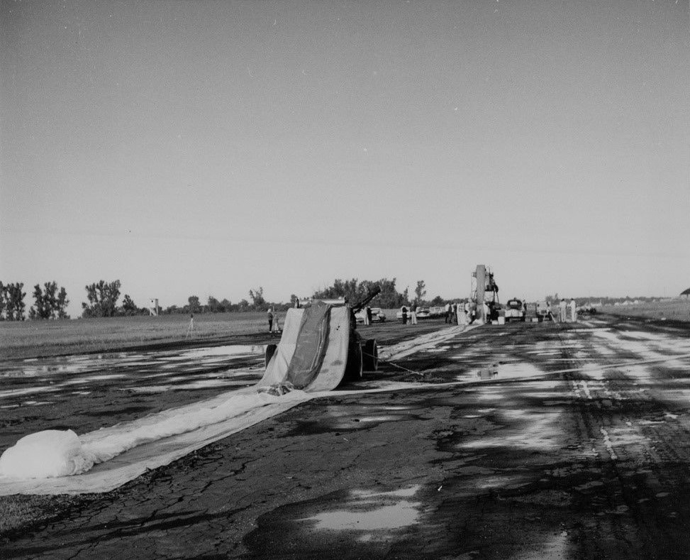
Launch site: University of Minnesota Airport, New Brighton, US
Balloon launched by: General Mills Inc.
Balloon manufacturer/size/composition: Zero Pressure Balloon 3.756.000 ft3
Flight identification number: GMI - 2232
End of flight (L for landing time, W for last contact, otherwise termination time): 6/28/1957 at ~ 13:40 cdt
Balloon flight duration (F: time at float only, otherwise total flight time in d:days / h:hours or m:minutes - ): 5 h 20 m
Landing site: In a farm, 6 miles SE of Maple Lake, Minnesota, US
Overall weight: 3600 pounds
The flight took place at the General Mills Flight Center near New Brighton, Minnesota, on June 28, 1957 at 8:03 CDT. At launch, the total suspended load was approximately 3,800 pounds, and a calculated free lift was added to produce a controlled initial rate of ascent.
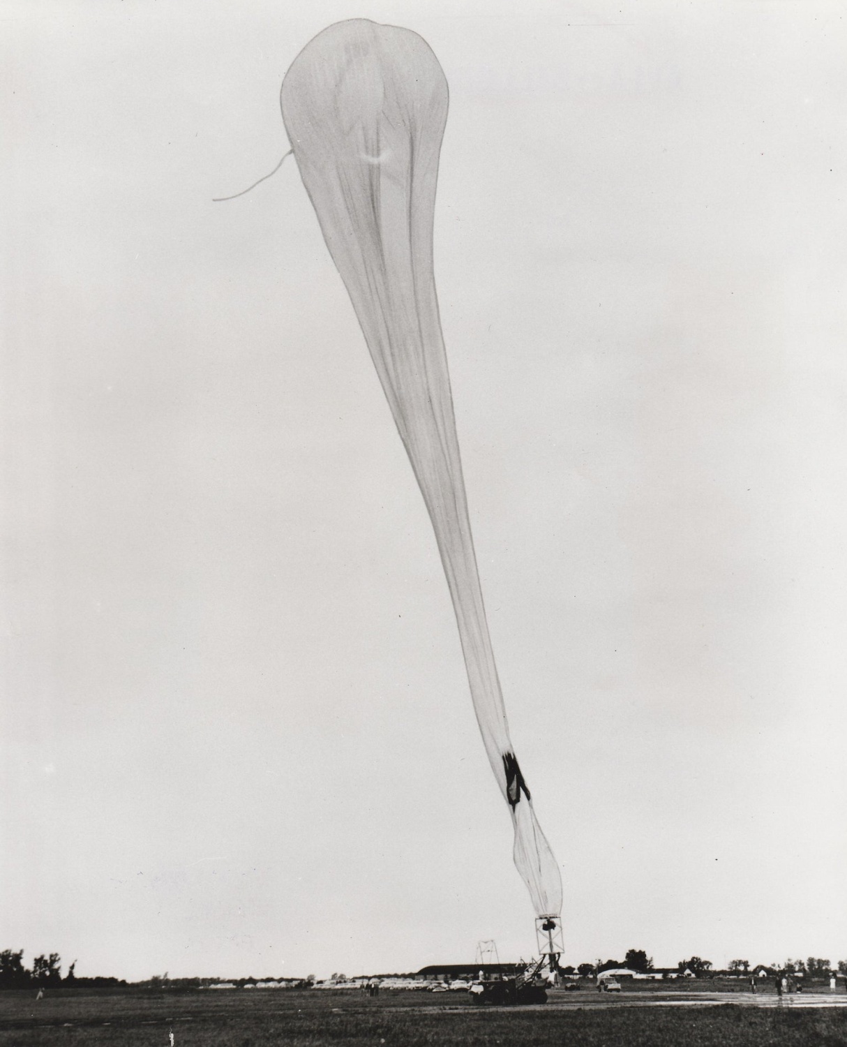
During the first phase of ascent, the balloon climbed at the expected rate until an unintended early release of ballast occurred due to a relay malfunction. This caused a rapid acceleration, with ascent rates increasing significantly and placing the balloon under more severe aerodynamic and pressure stresses than originally planned . As the balloon ascended through extreme altitudes, it experienced substantial superpressure and a pronounced valving event at approximately 105,000 feet. Despite these conditions, the envelope did not burst and instead demonstrated exceptional structural integrity. The balloon successfully exceeded its theoretical ceiling altitude and established a new record for balloon volume, confirming the robustness of the design and the reliability of its mechanical components.
The suspension system supporting the dummy rocket payload performed effectively throughout the flight. Photographic and mechanical observations showed that structural members were not overstressed and that the system maintained proper alignment. Although certain suspension features could not be fully tested without an active rocket, the configuration proved capable of withstanding the forces encountered during ascent, float, and descent, validating its suitability for future missions.
Multiple onboard cameras documented the relative orientation of the rocket and the balloon. The photographic record indicated that the rocket tip deviated only a few degrees from vertical during ascent and even less during the float phase, despite turbulence and high ascent velocities. During float, the rocket remained nearly vertical beneath the balloon apex, confirming that the load alignment and stabilization characteristics were better than anticipated.
Thermal data were collected from five strategically located sensors on the dummy rocket. These measurements showed that temperatures varied predictably with altitude, solar exposure, and component location. Internal temperatures within the plastic envelope remained within acceptable limits for most of the flight, while external components experienced lower temperatures, particularly during ascent. The recorded data provided a detailed profile of the thermal environment relevant to future operational payloads.
The launch system was tested under full load conditions and operated successfully. The rocket was rotated into the vertical position without binding, and the release mechanism functioned despite slight asymmetry during separation. The flexibility of the release system prevented damage to both the rocket and the supporting cage, demonstrating the practicality of the launch method for heavy, dynamically released payloads.
After completion of the high-altitude phase, the system descended under multiple parachutes. Recovery operations were executed promptly using ground vehicles and aerial tracking, and the payload was retrieved within a short time after landing. Only minor superficial damage was observed, and photographic documentation was obtained for all phases of assembly, launch, flight, and recovery. Overall, the mission successfully validated the balloon, suspension, launch, telemetry, photographic, and recovery systems and provided essential data for future high-altitude flights.
External references
- History of the Far Side project Stratopedia, the balloon encyclopedia
- Minneapolis Test Report - Project Far Side Mission report by General Mills Inc, July 1957
- Operation Farside Tested The Billings County Pioneer, August 15, 1957 Pag. 6
- Science: Rocket from Balloon TIME Magazine, Aug. 7 1957
- The Far Side Program Navigation, 6: 34-42, 1958
Images of the mission
If you consider this website interesting or useful, you can help me to keep it up and running with a small donation to cover the operational costs. Just the equivalent of the price of a cup of coffee helps a lot.
