Purpose of the flight and payload description
Project FAR SIDE was an experimental United States Air Force research effort conducted in 19561957 under the Air Force Office of Scientific Researchs Directorate of Advanced Studies, intended to probe the upper atmosphere and near-space environment using balloon-launched, multi-stage rockets. It was conceived in the context of growing Cold War interest in space and the Air Forces desire to remain a central actor in space research.
FAR SIDE adopted an unconventional and relatively inexpensive approach: a large helium balloon would lift a multi-stage rocket to altitudes of roughly 80,000-100,000 feet, from which it would be fired to reach distances of up to several thousand miles, carrying instruments to measure cosmic radiation and the Earths magnetic field. Since early 50's the so called Rockoon technique (contraption of ROCKet and ballOON) was used by several scientific groups that fired single-stage research rockets from stratospheric balloons launched from small vessels. However, the scale and complexity proposed by Far Side was a leap forward of several orders of magnitude.
Aeronutronic Systems, Inc., a subsidiary of the Ford Motor Company, served as the prime contractor for the rocket , General Mills designed and provided the massive polyethylene balloons while the University of Maryland was responsible for the scientific instrumentation onboard.
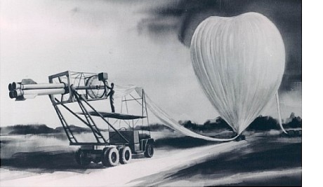
In the scheme at left we can see a detailed view of the entire launch system before flight (click for more details and diagrams)
The Balloon was a 3,750,000 cubic foot gas bag made of 2-mil polyethylene, designed and built by the Mechanical Division of General Mills to lift the 2,000-pound Far Side vehicle to 100,000 feet. The balloon weighed 1,500 pounds, measured 303 feet in length when slack, and had an inflated diameter of 204 feet. Its structure consisted of 80 panels with welded fortisan load tapes. At the top, the tapes were connected to a nylon rope forming a 7-foot-diameter window. At the bottom, the tapes were fitted with clips to attach to the rocket launchers load ring. The window design replaced a metal sealing device and allowed the vehicle to exit through the apex of the balloon when fired.
The Rocket launcher was a key component of the system. As the Far Side rocket was meant to be fired through the balloon, a light-weight aluminum box-type structure, consisting of a balloon load attachment ring at the forward end and a zero length launcher platform at the aft end, provided the means of handling and launching of the Far Side rocket. Launching arms pivoted from the box-type frame held the vehicle when in the near horizontal position during balloon inflation and launching operations, and in the vertical position during the balloon ascent. When fired, the launch arms were flipped clear of the frame by the forward motion of the vehicle, thereby preventing contact between the arms and the vehicle proper.
For safety purposes, the forward end of the vehicle was positioned by means of a special harness during handling and launching. The launch arm safety wires and the harness were removed by electrically fired cable cutters prior to actual firing of the first stage rocket engines.
Balloon instrumentation was mounted on the launcher structure and comprised three main components. First, a crystal-controlled radio command receiver with resonant reed relays activated the rocket engine ignition circuits. Second, a baro-transmitter transmitted altitude data during ascent and signaled the proper functioning of the radio receiver through a coded pressure signal. Third, an electric timer armed the firing circuit and served as a backup safety mechanism in case the radio command receiver failed.
The Far Side rocket was a four stage vector: first stage was powered by four solid propellant Recruit rocket engines supplied by the Thiokol Chemical Corporation; the second stage was a single Recruit engine; the third stage was a cluster of four Arrow II solid propellant rocket engines made by the Grand Central Rocket Co.; and the fourth stage, to which the instrument package was attached, was a single Arrow II rocket engine located within the third stage cluster. Overall length was 24 ft, gross weight at launch was 1.970 lbs, and the maximum velocity attained was 26.000 feet per second. Peak expected altitude was 4.060 miles.
At the extreme tip of the fourth stage was mounted the payload package, containing the experiment sensing instruments and the telemetry transmitter. The total payload weight was restricted to four pounds, including sensing instruments, telemetry transmitter, batteries, base plate, pressurized case (including nose heat sink) and antenna.
Two classes of scientific instruments were located onboard the fourth stage of the rocket: a Cosmic Rays Experiment whose primary objective was to measure the soft component of the cosmic rays by means of a geiger counter and a Magnetometer designed to measure absolute fields to about three percent and sharp changes to 1/2 of one percent. It worked on the principle that the voltage picked up in a rotating coil was proportional to the magnetic field.
Details of the balloon flight
Balloon launched on: 10/7/1957 at
Launch site: Eniwetok Air Base, Marshall Islands
Balloon launched by: General Mills Inc.
Balloon manufacturer/size/composition: Zero Pressure Balloon General Mills
Flight identification number: GMI - 2289
End of flight (L for landing time, W for last contact, otherwise termination time): 10/10/1957
Landing site: Rocket succesfully launched. 400 miles apogee confirmed.
Payload weight: 2400 lbs
Rocket succesfully launched. 400 miles apogee confirmed.
External references
- Farside project International missile and spacecraft guide, pag. 73, (1960)
- History of the Far Side project Stratopedia, the balloon encyclopedia
- Science: Rocket from Balloon TIME Magazine, Aug. 7 1957
- The Far Side Program Navigation, 6: 34-42, 1958
If you consider this website interesting or useful, you can help me to keep it up and running with a small donation to cover the operational costs. Just the equivalent of the price of a cup of coffee helps a lot.
