
Purpose of the flight and payload description
The BLIMP (Balloon Launched Integral Model Payload) was an instrument developed to test the detector design and onboard electronics of the IMAGER instrument proposed for the INTEGRAL gamma-ray astronomy mission. The balloon-borne prototype was designed to evaluate the performance of a position-sensitive gamma-ray detector and its associated signal acquisition, event processing, and telemetry systems. It was developed during the Phase A study by an international collaboration that included the Italian institutes TESRE/CNR Bologna, IFCTR/CNR Milano and DB2 Milano, with Rice Universitys Department of Space Physics and Astronomy leading the development.
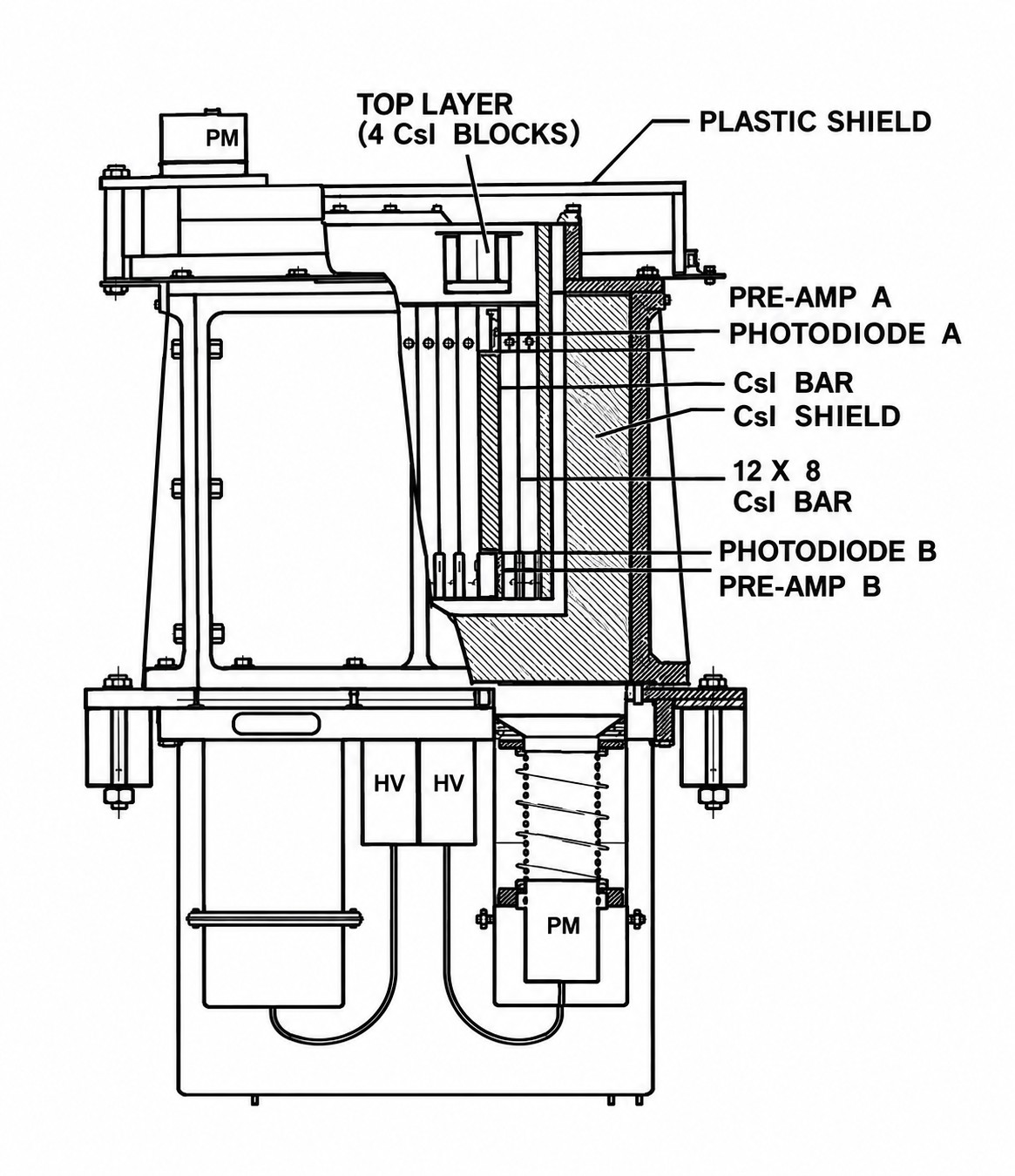
In the image at left we can see an scheme of the prototype (clcik to enlarge). The central detector, referred to as the calorimeter, consisted of 96 thallium-doped cesium iodide [CsI(Tl)] scintillator bars arranged in a 12 × 8 array. Each bar measured 15 × 1.3 × 1.3 cm and was coupled to two photodiodes, providing 192 analog readout channels. The instrument was designed to operate over an energy range of approximately 15 keV to 10 MeV. The two photodiode signals associated with each bar were processed to determine the deposited energy and identify the interaction position.
The onboard electronics comprised three main subsystems: Analog Front-End Electronics (AFEE), Digital Processing Electronics (DPE), and the Data Processing Unit (DPU). These subsystems were arranged hierarchically, with detector signals processed by the lower-level electronics before event handling, instrument control, and telemetry operations.
The AFEE consisted of 192 amplification chains associated with the photodiode channels. Preamplifiers were mounted close to the photodiodes to reduce electronic noise. Each chain included amplification, pulse shaping, and signal stretching. Threshold discriminators identified signals exceeding predefined levels and initiated the acquisition process. Signals from the two photodiodes associated with each bar were combined for threshold comparison.
The DPE performed channel identification, event timing, analog-to-digital conversion, and temporary data storage. Following a detector trigger, programmable timing windows determined which signals were associated with the same event and controlled the acquisition and reset sequence. Fast address encoders identified the responding detector bars, while multiplexers selected the corresponding analog signals for digitization. The conversion electronics included dual-slope amplifiers, programmable-gain amplifiers, and 12-bit analog-to-digital converters. The 192 channels were divided into two groups of 96, each processed by a separate conversion chain. Event records were stored in first-in, first-out (FIFO) memory, containing timing, energy, and detector-position information. Signals from the anticoincidence shields could be used to flag or reject events.
The DPU processed the event records, monitored detector counting rates, controlled individual bars, and managed communication with the ground station. Its input data processor used a parallel, pipelined architecture to read and organize event records. Approximately 200 counters were implemented to monitor the counting rates of the detector bars. The on/off bar controller allowed individual channels to be disabled through telecommands. The Master Control System (MCS), based on two Intel 80186 microprocessor boards, handled telecommand decoding, housekeeping data, telemetry formatting, and communication with the ground station.
The digital electronics used erasable programmable logic devices and Xilinx field-programmable gate arrays (FPGAs). The programmable architecture allowed digital functions to be modified without redesigning the circuit boards. The complete AFEEDPEDPU processing chain was designed to handle approximately 10,000 events per second.
The onboard system formatted the processed event data for transmission through a pulse-code-modulated telemetry link. Telemetry bit rate and integration time could be selected to accommodate the available transmission capacity. The ground support equipment included computers for data acquisition, analysis, display, and telecommand generation.
Details of the balloon flight
Balloon launched on: 10/27/1993 at 13:38 utc
Launch site: Scientific Flight Balloon Facility, Fort Sumner, (NM), US
Balloon launched by: National Scientific Balloon Facility (NSBF)
Balloon manufacturer/size/composition: Zero Pressure Balloon SF3-317.60-080-NSCHR-ST
Balloon serial number: W11.82-1-12
Flight identification number: 373N
End of flight (L for landing time, W for last contact, otherwise termination time): 10/27/1993 at 17:04 utc
Landing site: 3 miles NE of Gotebo, Oklahoma, US
The balloon was launched from the Scientific Balloon Flight Facility in Fort Sumner, New Mexico on October 27, 1993 at 13:38 UTC. Total flight time was about 4 hours at an altitude of 40 km. Flight was terminated that same day at 17:04 UTC and the payload landed 3 miles NE of Gotebo, Oklahoma. During the flight, increased noise in the onboard data pattern was observed. The instrument was switched by telecommand to an operating mode that retained anticoincidence shield operation but disabled onboard event rejection. The resulting data contained a high proportion of noise and required post-flight analysis.
The flight demonstrated that the instruments reconfigurable digital electronics could be controlled remotely and that telecommands could be used to change the operating mode in response to an unexpected condition.
External references
- Annual Reports of Astronomical Observatories and Departments: Rice University, William Marsh, Department of Space Physics and Astronomy Bulletin of the American Astronomical Society, Vol. 27, p.554
- NASA Balloon Flights (19891998) in NASA Historical Data Book, Vol. VII: NASA Launch Systems, Space Transportation, Human Spaceflight, and Space Science, 1989-1998
- On-board electronics for BLIMP: a balloon-borne prototype for the INTEGRAL satellite IEEE Conference on Nuclear Science Symposium and Medical Imaging, 1992, pp. 652-653 vol.1
- On-board electronics for BLIMP: a balloon-borne prototype for the INTEGRAL satellite IEEE Transactions on Nuclear Science, vol. 40, no. 4, pp. 909-912, Aug. 1993
- The INTEGRAL mission Memorie della Società Astronomia Italiana, Vol. 64, p.713
StratoCat is an independent, non-commercial project maintained to preserve and share the history of scientific and stratospheric ballooning. If you find the site useful, you can help keep it running with a small donation toward its operating costs. Every contribution, even the equivalent of a cup of coffee, is greatly appreciated.